
Bone conduction device

A technology of bone conduction and bone conduction vibrator, which is applied in the direction of bone conduction transducer hearing equipment, sensors, sensor components, etc. It can solve the problems of lack of saturation frequency bands, great gaps, and monotonous sound, etc., and achieve perfect timbre and sound quality , reduce battery capacity, and enhance the effect of realizing space

Inactive Publication Date: 2019-07-30
宋佳
View PDF0 Cites 2 Cited by
  • Summary
  • Abstract
  • Description
  • Claims
  • Application Information

AI Technical Summary

Problems solved by technology

[0007] Since the civilian use of bone conduction technology has not been promoted on a large scale, the existing bone conduction devices on the market often stay at the stage of "usable", that is, they can be guaranteed to be used. Research and development, but the technology that can be commercially transformed is mainly focused on the structural design of bone conduction devices and the development of new products, and there has been no leapfrog development
Commonly used materials in bone conduction devices are general-purpose materials such as rubber, plastic, conventional metal materials, or other composite materials. The performance of the above-mentioned general-purpose materials is limited, and it is difficult to produce excellent acoustic effects when applied to bone conduction devices. The acoustic effect is far from other existing devices, especially in the sound transmitted by the bone conduction device, the more saturated frequency band is missing, resulting in monotonous sound, poor use effect, and it is difficult to hit the higher-end sound generator market. The defects cannot be improved by the method of structural design

Method used


Image

  • Bone conduction device
  • Bone conduction device
  • Bone conduction device

Examples


Embodiment 1

[0033] Example 1 Piezoelectric bone conduction device

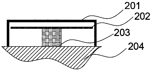
[0034] Piezoelectric bone conduction device is a device that uses the inverse piezoelectric effect of piezoelectric ceramics to conduct sound transmission. The piezoelectric vibrator is directly driven by an electrical signal with audio frequency, and vibration is generated through the mechanical deformation of the piezoelectric vibrator. The vibration is transmitted to the human body through the skull. The cochlea to perceive sound. The piezoelectric vibrator is the most important core structure in the piezoelectric bone conduction device. The bone conduction device using the piezoelectric vibrator generally has a resonance frequency of 1KHz or higher, so the occurrence of the low frequency region of the piezoelectric bone conduction device is easy. Insufficient reproduction, how to fully conduct conduction in the low-frequency region is the research focus of piezoelectric bone conduction devices.

[0035] Piezoelectric...

Embodiment 2

[0039] Example 2 Electromagnetic bone conduction device

[0040] The principle of the electromagnetic bone conduction device is similar to that of the piezoelectric type, except that the bone conduction vibrator is a composite structure of magnets.

[0041] as attached image 3 Shown is a schematic diagram of the simple structure of the electromagnetic bone conduction device. The bone conduction device mainly includes a bone conduction vibrator 304, a fixed structure 302 arranged on both sides of the bone conduction vibrator, a protective front shell 301, and a protective rear shell 303, wherein any one of the protective front and rear shells can be used as a conduction conductor at the junction with the human body. The material is the same as the conduction column 203 in Embodiment 1.

[0042] The above-mentioned structures can all be made of amorphous alloy materials or partially made of amorphous alloy materials, and some of them are made of amorphous alloy materials, whe...

Embodiment 3

[0045] In a piezoelectric bone conduction device or an electromagnetic bone conduction device, one or more of its internal or external skeleton structure, external shell structure or connection structure is made of amorphous alloy or partially made of amorphous alloy, For example, the connection part in the middle of the rear-mounted bone conduction earphone (overall structure), the outer shell and inner shell that protect the sound transmission components on both sides, etc., in these components that are only used as structural parts, the proportion of amorphous alloys in terms of volume, Greater than or equal to 10% of the overall metal material component can meet the demand, and the proportion of amorphous state can be increased according to the use requirements, up to 90% (too high amorphous content puts higher demands on the amorphous alloy manufacturing process requirements, the cost of preparation soars). The thickness of metal material components made of amorphous allo...


PUM

PropertyMeasurementUnit
Vickers hardnessaaaaaaaaaa
tensile strengthaaaaaaaaaa
yield strengthaaaaaaaaaa

Abstract

The invention discloses a bone conduction device. A metal material assembly in the bone conduction device is completely or partially an amorphous alloy, and the amorphous alloy is one or more of a zirconium-based amorphous alloy, a rare earth-based amorphous alloy, a copper-based amorphous alloy, a titanium-based amorphous alloy, an aluminum-based amorphous alloy and a magnesium-based amorphous alloy. According to the device, the sound quality transmitted by the bone conduction device is better. The deformation amount realized in the amorphous alloy deformation process can conduct different tone quality effects. The device has stronger realization space in the aspect of sound quality, so that a wearer can obtain better sound quality level by changing, and the sound effect and the sound quality which can be obtained by other conventional materials such as heavy background sound, high pitch and the like through higher deformation force can be obtained by using amorphous alloy of a specific system without changing the overall structural design.

Description

technical field [0001] The invention belongs to the field of new materials, and in particular relates to a bone conduction device. Background technique [0002] The auditory system is an important sensory organ for human beings to receive external signals. Under normal circumstances, the sound wave generated by the vibration of the sound source is transmitted to the inner ear through two channels: one is transmitted to the inner ear through the external auditory canal, the tympanic membrane and the ossicle chain composed of three ossicles, that is, the air conduction of the sound wave. It is the main conduction path of normal hearing; the second is to transmit directly to the inner ear through the skull, that is, bone conduction, which has little effect under normal physiological conditions. [0003] The main way of bone conduction to transmit sound is that the sound passes through the skull to vibrate the cochlea wall. There are two main conduction modes: [0004] First, ...

Claims


Application Information

Patent Timeline
Patent Type & Authority Applications(China)
IPC IPC(8): H04R1/10H04R1/08G02C11/00
CPCG02C11/00H04R1/08H04R1/1091H04R2460/13
Inventor 宋佳
Owner 宋佳
Learn More