
High current ion high voltage static accelerating tube

A high-voltage electrostatic and accelerating tube technology, which is applied in the direction of DC voltage accelerators, electrical components, accelerators, etc., can solve the problems of beam emittance increase, pressure gradient drop, accelerated beam current intensity, etc., to suppress beam emission degree, suppress beam divergence, and improve the effect of withstand voltage level

Active Publication Date: 2019-07-30
HEFEI INSTITUTES OF PHYSICAL SCIENCE - CHINESE ACAD OF SCI
View PDF10 Cites 3 Cited by
  • Summary
  • Abstract
  • Description
  • Claims
  • Application Information

AI Technical Summary

Problems solved by technology

[0005] In the traditional high-voltage electrostatic accelerating tube design process, the withstand voltage level of the accelerating tube is limited by vacuum breakdown, which is mainly manifested in the following two aspects: 1) The withstand voltage gradient of the accelerating tube will increase with the increase of the total voltage of the accelerating tube 2) When the voltage reaches a certain threshold, a large amount of electron flow will suddenly appear in the accelerating tube, accompanied by strong X-rays. If the voltage continues to increase, the electron flow will increase sharply and soon exceed the load of the high-voltage generator capability, thus limiting further increases in voltage
At the same time, when the beam intensity accelerated by the accelerating tube is further increased, the nonlinear part of the strong space charge effect will cause the beam emittance to increase, so that the beam envelope of the high-current ion beam is too large and is lost in the accelerating tube. On the wall of the insulator or on the accelerating electrode, a large number of secondary electrons are generated, thereby destroying the withstand voltage level of the accelerating tube and limiting the acceleration of the accelerated beam current intensity of the accelerating tube

Method used


Image

  • High current ion high voltage static accelerating tube
  • High current ion high voltage static accelerating tube

Examples


Embodiment 1

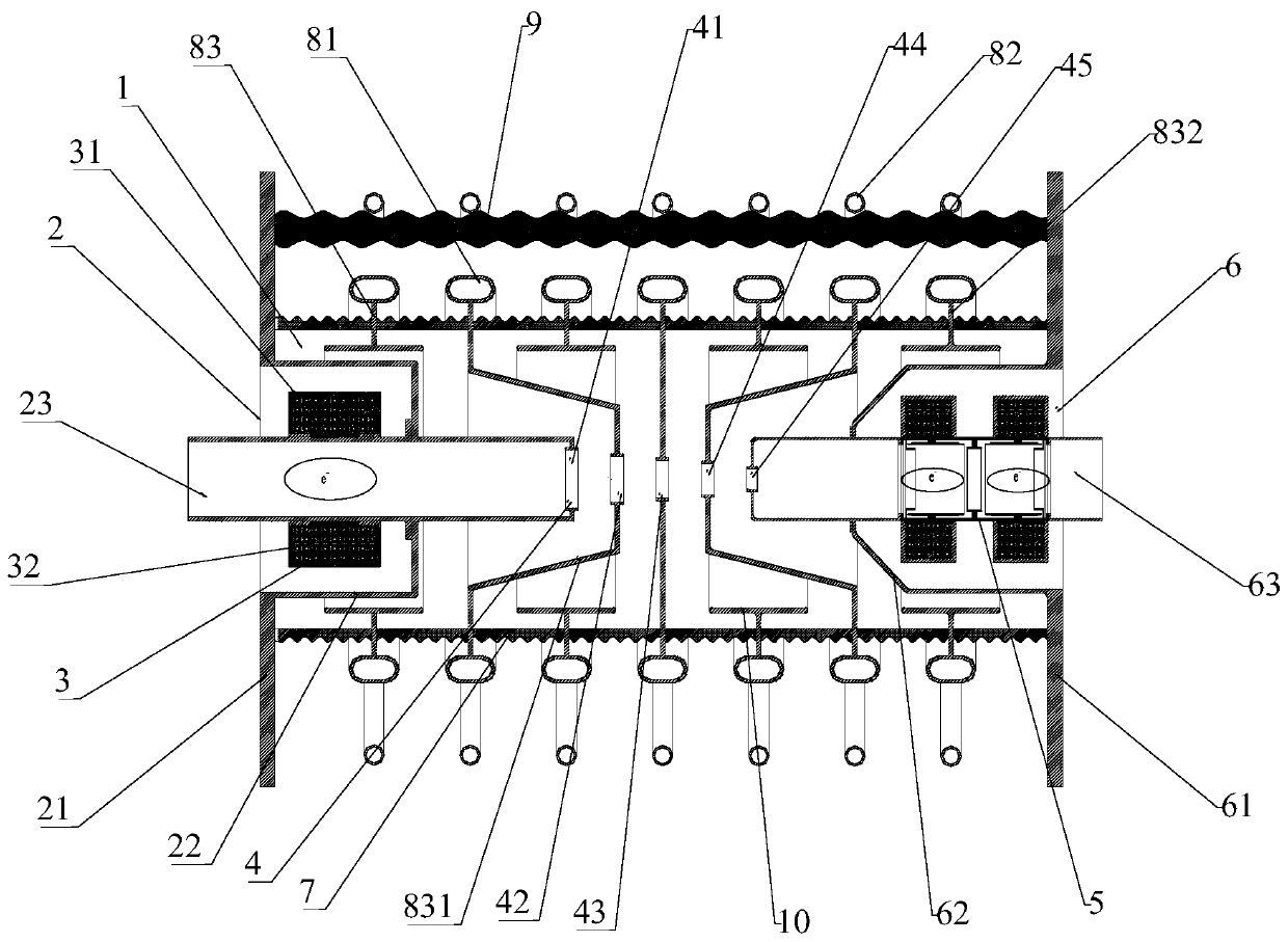
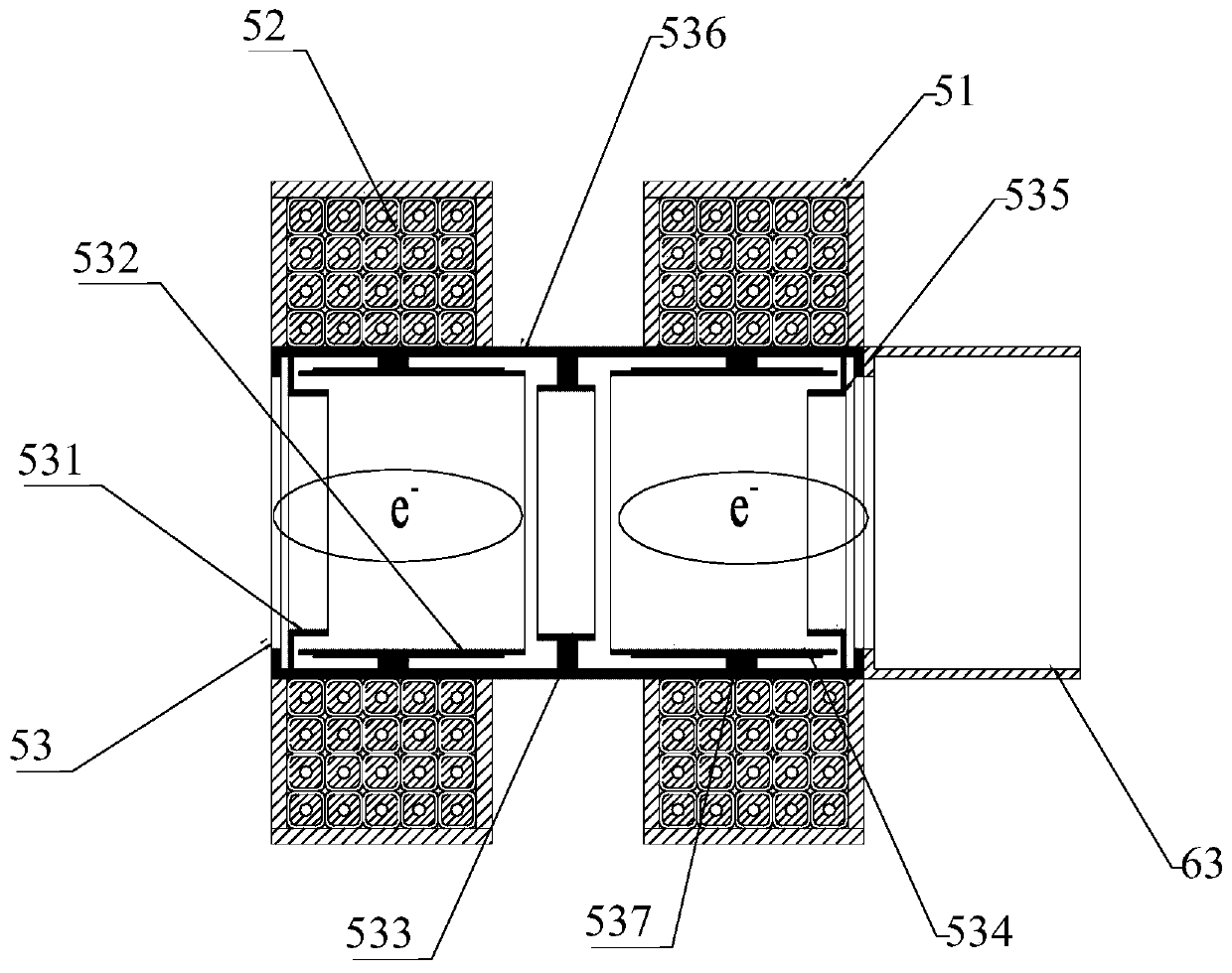
[0032] Such as Figure 1-2 As shown, a strong ion high-voltage electrostatic accelerating tube of this embodiment includes an accelerating tube body 1 . The inside of the accelerating tube body 1 is provided with an accelerating tube inlet 2, a magnetic mirror device 3, an accelerating electrode 4, a double-electron cloud space charge lens device 5 and an accelerating tube outlet 6 in sequence along the ion beam transport direction. The entrance 2 of the acceleration tube and the exit 6 of the acceleration tube are also provided with an inlet flange 21 and an outlet flange 61 respectively. The function of the inlet flange 21 is mainly used for the connection between the beam pipe of the low-energy transmission section and the body 1 of the acceleration tube. . Wherein, the rear end of the inlet flange 21 and the front end of the outlet flange 61 are respectively connected with the inlet flange jacket 22 and the outlet flange jacket 62, and the middle parts of the inlet flange...


PUM


Abstract

The invention provides a high current ion high voltage static accelerating tube comprising an accelerating tube body; the accelerating tube body specifically comprises an entrance cylinder, an inlet flange, an inlet flange jacket, a magnetic lens device, an accelerating electrode, a double electron cloud space charge lens device, an outlet flange jacket, an outlet flange, an outlet cylinder, an insulating ring, an equalizing ring and an insulating column; the magnetic lens device is arranged between the inlet flange jacket and the entrance cylinder; the double electron cloud space charge lensdevice is arranged between the outlet flange jacket and the outlet cylinder; and the radius of the central round hole of each accelerating electrode is sequentially reduced along a beam transmission direction. According to the high current ion high voltage static accelerating tube, by using the interaction of the focusing electric field and beam-plasma, the ion focusing forces of the acceleratingarea and accelerating tube entrance area are separately enhanced, the beam dispersion caused by a strong space charge effect under the condition of high current ion beam is suppressed, the beam loss is reduced, the increasing of beam emittance is suppressed, and the efficient and stable acceleration of the high current ion beam can be achieved.

Description

technical field [0001] The invention relates to the technical field of particle accelerators, in particular to a high-voltage electrostatic acceleration tube for strong current ions. Background technique [0002] With the continuous development of science and technology, particle accelerator science and technology has made great achievements, and its application scope has gradually moved from the field of basic research to all fronts of industry, agriculture, medicine and national defense construction. Especially the recently developed accelerator-driven advanced nuclear energy system has gradually become a research hotspot in various countries. [0003] An accelerator is a device that artificially generates beams of high-energy charged particles. It uses a certain form of electromagnetic field to accelerate charged particles such as positive and negative electrons, protons, light and heavy ions to keV, MeV, GeV, TeV or higher energies. This kind of ion beam with relativel...

Claims


Application Information

Patent Timeline
IPC IPC(8): H05H5/03
CPCH05H5/03
Inventor 吴宜灿王永峰刘超王志刚张青鵾
Owner HEFEI INSTITUTES OF PHYSICAL SCIENCE - CHINESE ACAD OF SCI
Features
  • Generate Ideas
  • Intellectual Property
  • Life Sciences
  • Materials
  • Tech Scout
  • Unparalleled Data Quality
  • Higher Quality Content
  • 60% Fewer Hallucinations
Learn More