
Special numerically-controlled machine tool for machining axle type parts

A technology of CNC machine tools and parts, applied in the field of CNC machine tools, can solve problems such as affecting processing efficiency, difficulty in axial measurement, and unguaranteed dimensional accuracy, and achieve the effects of reasonable structure, relative coincidence accuracy, and simple structure

Pending Publication Date: 2019-08-02
宁夏长兴精密机械有限公司
View PDF0 Cites 4 Cited by
  • Summary
  • Abstract
  • Description
  • Claims
  • Application Information

AI Technical Summary

Problems solved by technology

When processing long-axis parts with complex procedures such as the axle of a truck, the processing procedures are: processing both ends, outer circles and inner holes at both ends, so it needs to be processed in two processes without disassembling the workpiece. The first process clamps the outer circle to process the end face and inner hole, and the second process the tailstock withstands the inner holes at both ends of the workpiece to process the outer circle. When using the existing double-headstock CNC lathe to process the above-mentioned shaft parts, the main problems are as follows A few points: 1. The tailstocks at both ends of the existing double-spindle box machine tools are fixed. When loading and unloading long-axis parts, it is necessary to manually use a crane for loading and unloading, which seriously affects the processing efficiency; 2. Because some long-axis parts The part has requirements on the axial dimension between the shoulders at both ends. During the processing, since the measurement parts of the two shoulders are located at the left and right ends of the two headstocks, it is difficult to measure the axial direction, and the dimensional accuracy cannot be guaranteed.

Method used


Image

  • Special numerically-controlled machine tool for machining axle type parts
  • Special numerically-controlled machine tool for machining axle type parts
  • Special numerically-controlled machine tool for machining axle type parts

Examples


Embodiment Construction

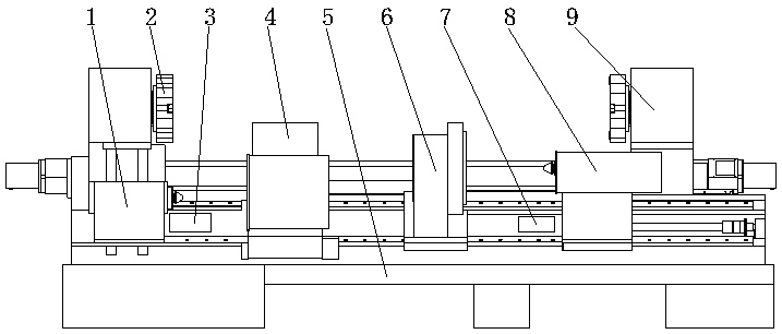
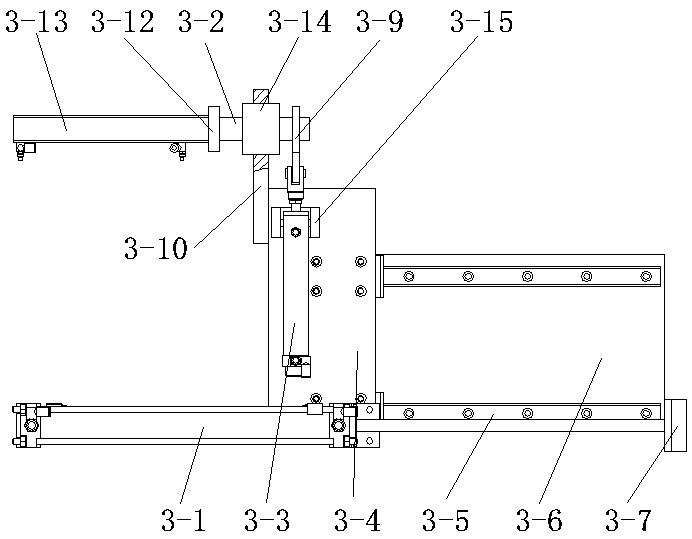
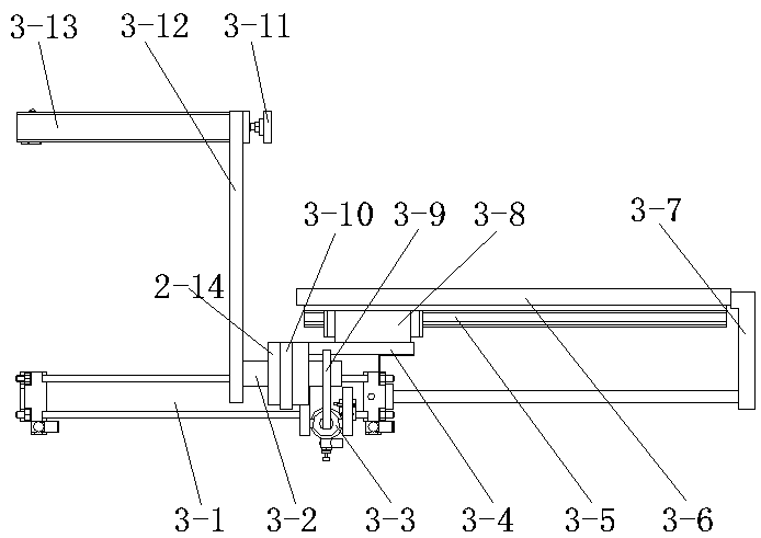
[0031] exist Figures 1 to 15Among them, 1 is the left tailstock, 1-1 is the tailstock body, 1-1-1 is the tailstock sleeve, 1-1-2 is the mandrel, 1-2 is the tailstock sliding body, 1-3 is the base , 1-4 is the guide rail, 1-5 is the tailstock locking device, 1-5-1 is the lower piston rod, 1-5-2 is the piston, 1-5-3 is the reset spring, 1-6 is the pressure plate , 1-7 is the driving device, 1-7-1 is the adjustment plate, 1-7-2 is the end cover, 1-7-3 is the cavity, 1-7-4 is the partition, 1-7-5 is the Piston Ⅰ, 1-7-6 is the sealing flange, 1-7-7 is the adjusting bolt, 1-8 is the sleeve locking device, 1-8-1 is the oil inlet, 1-8-2 is the piston Ⅱ , 1-8-3 is the compression spring, 1-9 is the positioning device of the tailstock slider, 1-9-1 is the piston rod, 1-9-2 is the piston III, 1-9-3 is the positioning pin, 1- 9-4 is the positioning block, 1-10 is the oil cylinder, 1-10-1 is the piston rod I, 2 is the left tool table, 3 is the left axial length measuring device, 3-1 is ...


PUM


Abstract

The invention relates to a numerically-controlled machine tool, in particular to a special numerically-controlled machine tool for machining axle type parts. The special numerically-controlled machinetool comprises a tool body, two spindle boxes mounted on the tool body, two tailstocks, two knife posts and a machine tool electrical control device; one of the tailstock can move up and down; supporting barrels are fixedly mounted in spindle holes in the spindle boxes; universal balls are fixed to the inner walls of the supporting barrels; and workpiece axial measurement devices are mounted on two sides of the two spindle boxes. According to the technical scheme, on the basis of an existing two-spindle numerically-controlled machine tool, the structures in the tailstock and the spindle on one side are improved so as to meet the requirements for loading and unloading as well as accurate axial length measurement of long axle type parts relatively large in length-diameter ratio, meanwhile,left-side and right-side axial length measurement devices are added to the machine tool, through the improvement and the addition, the loading and unloading time for the long axle type parts can be shortened effectively, the axial size measurement accuracy can be improved, and automatic loading, unloading, and size measurement can be realized.

Description

technical field [0001] The invention relates to a numerically controlled machine tool, in particular to a special numerically controlled machine tool for processing axle parts. Background technique [0002] At present, when machining shaft parts, double spindle box CNC lathes are widely used due to their high machining efficiency and high machining accuracy. When processing long-axis parts with complex procedures such as the axle of a truck, the processing procedures are: processing both ends, outer circles and inner holes at both ends, so it needs to be processed in two processes without disassembling the workpiece. The first process clamps the outer circle to process the end face and inner hole, and the second process the tailstock withstands the inner holes at both ends of the workpiece to process the outer circle. When using the existing double-headstock CNC lathe to process the above-mentioned shaft parts, the main problems are as follows A few points: 1. The tailstock...

Claims


Application Information

Patent Timeline
IPC IPC(8): B23B3/06B23B3/30B23B5/08B23B23/00B23B25/06B23B15/00
CPCB23B3/06B23B3/30B23B5/08B23B23/00B23B25/06B23Q7/00
Inventor 施文秀于学奎杜武李刚王菊芳李旭
Owner 宁夏长兴精密机械有限公司
Learn More