
Construction method of subway station continuous wall

A technology for subway stations and construction methods, applied in sheet pile walls, infrastructure engineering, construction, etc., can solve problems such as endangering the safety of buildings and underground pipelines, land subsidence, collapse, and unfavorable tank wall stability, and achieves guaranteeing the construction progress. Strong bearing capacity and the effect of reducing hidden dangers of quality

Inactive Publication Date: 2019-08-02
广州穗岩土木科技股份有限公司
View PDF4 Cites 0 Cited by
  • Summary
  • Abstract
  • Description
  • Claims
  • Application Information

AI Technical Summary

Problems solved by technology

[0005] During the construction process, especially in the rainy season, the precipitation causes the groundwater table to rise sharply, resulting in water accumulation on the ground, and the accumulated water seeps into the tank to dilute the mud, causing a large amount of mud to leak into the gaps in the foundation, and the mud liquid level drops, which is not conducive to the tank. The stability of the wall will easily lead to the collapse of the tank wall, and the collapse of the tank wall will cause the wall concrete to exceed the allowable limit and the structural size, and even cause the adjacent ground to subside and collapse, endangering the safety of adjacent buildings and underground pipelines. serious consequences

Method used


Image

  • Construction method of subway station continuous wall
  • Construction method of subway station continuous wall
  • Construction method of subway station continuous wall

Examples


Embodiment Construction

[0042] The present invention will be described in further detail below in conjunction with the accompanying drawings.

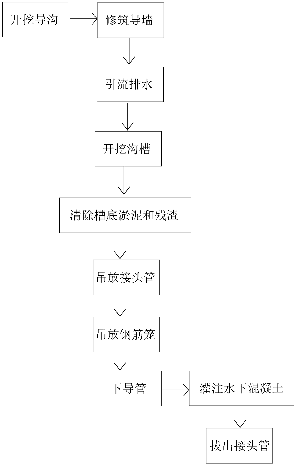
[0043] refer to figure 1 , is the construction method of a kind of subway station diaphragm wall disclosed by the present invention, comprises the following steps:

[0044] 1) Excavation of guide ditch: Level the site, put in the control points of each main axis according to the closed wire and reference point around the foundation pit, use a total station to measure and position, measure and position each axis, and then close the periphery of the foundation pit The conductors, reference points, and control points are measured and calibrated multiple times until the error value is within the preset range, and then the guide trench is excavated and the spoil is disposed of.

[0045] Level the site to remove obstacles and keep the excavation surface flat, which is beneficial for measuring and positioning the position of the guide wall 1 .

[0046] 2) Build gu...


PUM


Abstract

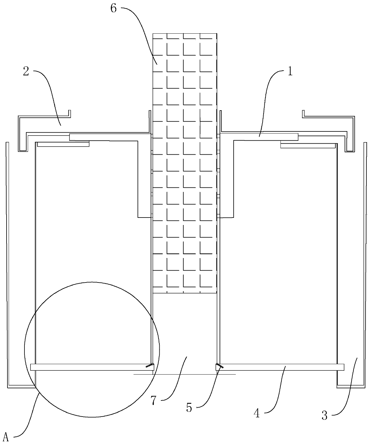
The invention relates to the technical field of subway station continuous wall construction, and aims to provide a subway station continuous wall construction method, which is characterized by comprising the following steps of: 1) excavating a guide ditch, namely leveling a site, measuring and positioning, excavating the guide ditch and treating spoil; 2) constructing a guide wall: binding reinforcing steel bars and supporting a formwork, pouring concrete to construct the guide wall, and removing the formwork; 3) performing drainage: making the top of the guide wall detachably connected with adrainage pipe, and making the tail end of the drainage pipe connected with a water collecting well; 4) excavating a trench: excavating the trench by utilizing a trench excavating machine according tothe geological condition of a trench forming place, the structure, the size, the quality requirement and the like of an underground wall; 5) removing sludge and residues on the bottom of the trench:after the groove is formed, replacing and removing the mud on the groove bottom of the groove; 6) building a communicating pipe between the water collecting well and the groove, covering the end, close to the groove, of the communicating pipe with a baffle in a sealed mode, wherein the baffle is arranged in a hinged mode and only moves in the direction of the water collecting well. The method is suitable for subway station continuous wall construction.

Description

technical field [0001] The invention relates to the technical field of underground diaphragm wall construction, more specifically, it relates to a method for constructing a diaphragm wall of a subway station. Background technique [0002] The underground diaphragm wall is a continuous underground reinforced concrete wall, which is used as the enclosure structure of the subway station construction to protect the safety of the foundation pit and surrounding areas of the underground station. Due to its high rigidity, it can not only withstand the lateral pressure acting on the wall, but also has the function of water-retaining and anti-seepage, and can also be used as a part of the underground subway station, and has been widely used in subway projects. [0003] The underground diaphragm wall is used as the side wall of the subway station, and there are two types: single-layer wall and double-layer wall. The underground diaphragm wall of the single-layer side wall is used not ...

Claims


Application Information

Patent Timeline
IPC IPC(8): E02D5/18
CPCE02D5/18
Inventor 王欢
Owner 广州穗岩土木科技股份有限公司
Learn More