Permanent-magnet novel electromagnetic relay

An electromagnetic relay, permanent magnet technology, applied in the direction of electromagnetic relay, electromagnetic relay details, relays, etc., can solve the problems of high power requirements, poor economy and controllability, shortened life of relays, etc., to meet the requirements of mechanical characteristics , excellent load output characteristics, and good anti-interference performance

Active Publication Date: 2019-08-02
GUILIN UNIV OF ELECTRONIC TECH
View PDF6 Cites 4 Cited by
  • Summary
  • Abstract
  • Description
  • Claims
  • Application Information

AI Technical Summary

Problems solved by technology

However, there are many mechanical parts, high failure rate, and large time dispersion.
Although the electromagnetic mechanism can better meet the requirements of electromagnetic relays, its magnetic circuit inductance is large, the operating current is large, the power requirements for the power supply are high, the economy and controllability are relatively poor, and the response time of the operation is scattered. The AC control signal is generally large, and even if the dwell operation is used, the control time dispersion is above the millisecond level
[0003] Traditional electromagnetic relays are limited by their own manufacturing technology, especially the small contact gap. When connecting high-voltage AC, high-voltage DC, large DC motors, and low power factor inductive loads, the relay contacts are very prone to bonding failure or continuous arcing. Problems such as the failure of the ignition contact system will easily lead to a greatly shortened life of the relay, so it is necessary to improve it

Method used


Image

  • Permanent-magnet novel electromagnetic relay
  • Permanent-magnet novel electromagnetic relay
  • Permanent-magnet novel electromagnetic relay

Examples


Embodiment Construction

[0027]In order to make the objectives, technical solutions and advantages of the present invention clearer and clearer, the technical solutions in the embodiments of the present invention will be clearly and completely described below in conjunction with specific embodiments and with reference to the accompanying drawings. It should be noted that the described embodiments of the present invention are illustrative but not restrictive of the present invention, and thus the present invention is not limited to the above-described embodiments. Based on the principles of the present invention, all other implementations obtained by those skilled in the art without creative efforts are deemed to be within the protection of the present invention.

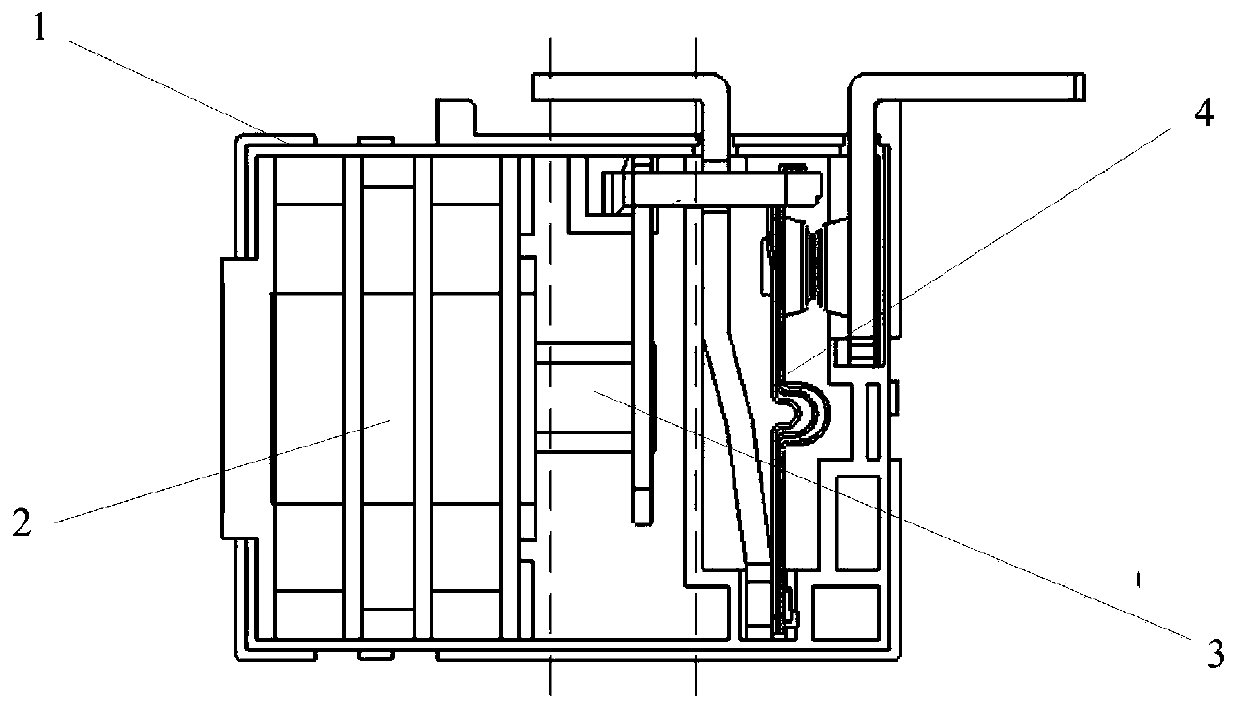
[0028] Such as figure 1 As shown, a new permanent magnet electromagnetic relay includes a housing 1, an electromagnetic-permanent magnet system 2, a drive mechanism 3 and a contact system 4. The electromagnetic-permanent magnet system 2, th...


PUM


Abstract

The invention discloses a permanent-magnet novel electromagnetic relay, and belongs to the technical field of electromagnetic relays. The permanent-magnet novel electromagnetic relay comprises a housing, an electromagnetic-permanent magnet system, a driving mechanism and a contact contacting system, wherein the electromagnetic-permanent magnet system, the driving mechanism and the contact contacting system are arranged in the housing, one end of the driving mechanism moves in the electromagnetic-permanent magnet system, and the other end is connected with the contact contacting system. According to the invention, the electromagnetic-permanent magnet system and the contact contacting system are combined, an electromagnetic force provided by the electromagnetic-permanent magnet system is converted into a pushing force of the contact contacting system, then the contact is stabilized at the limit position according to the magnetic force of the permanent magnet, and the working stability ofthe electromagnetic relay is improved. The electromagnetic relay of the invention can effectively provide a great pushing force, has the characteristics of simple structure, small volume, good assembly and good manufacturability, and has broad market prospects in the application and popularization of electrical circuits.

Description

technical field [0001] The invention relates to the technical field of electromagnetic relays, in particular to a novel permanent magnet electromagnetic relay. Background technique [0002] With the rapid development of green energy, ensuring the security of integrated energy systems and promoting the energy Internet, the smart grid, which is characterized by informatization, automation and interaction, has become a hot issue in the international power industry research. Automation has been gradually carried out in various fields. In order to ensure the safety of electricity consumption and output power, the requirements for switching voltage and switching current of relays are getting higher and higher, such as: electric vehicles, hybrid vehicles, fuel cell vehicles, construction machines, power supplies Management, charging-discharging equipment, frequency conversion control, solar power generation system control, welding equipment, elevators and other occasions; tradition...

Claims


Application Information

Patent Timeline
Patent Type & Authority Applications(China)
IPC IPC(8): H01H50/64H01H51/06
CPCH01H50/64H01H51/06
Inventor 范兴明张伟杰张鑫李震刘华东
Owner GUILIN UNIV OF ELECTRONIC TECH
Why Eureka
Try Eureka