Horizontal and vertical switching rolling mill for bar finish rolling

A technology of horizontal rolling mill and vertical rolling mill, which is applied to the driving device of metal rolling mill, metal rolling stand, metal rolling mill stand, etc., which can solve the problems of large vibration of rolling mill, increased resistance, deformation of stand, etc., to achieve Guaranteed dimensional accuracy, improved production efficiency, and stable high-speed operation

Inactive Publication Date: 2019-08-06
北京科技大学设计研究院有限公司
View PDF5 Cites 2 Cited by
  • Summary
  • Abstract
  • Description
  • Claims
  • Application Information

AI Technical Summary

Problems solved by technology

After long-term use, due to factors such as frame deformation, it is difficult to adjust the concentricity
In addition, as the main support for the rotation, the wear of the guide wheel groove in the C-frame and the deformation of the C-frame both increase resistance to the rotation process, and it takes time and effort to rotate once, and the high-speed operation of the rolling mill has a large vibration
Due to the rotation to the ground deeper, reaching -3m, the design of the drainage ditch is deeper
Although the type (3) has no rotation process, since the reversing bevel gearbox and its long axis of the vertical rolling mill and the universal joint shaft of the horizontal rolling mill are all under the platform foundation of the vertical rolling mill, installation and maintenance are very inconvenient
In addition, because the compound gearbox is installed outside the foundation platform of the vertical rolling mill, the universal joint shaft of the horizontal rolling mill is relatively long, and the vibration of the rolling mill is large when the rolling mill runs at high speed

Method used


Image

  • Horizontal and vertical switching rolling mill for bar finish rolling
  • Horizontal and vertical switching rolling mill for bar finish rolling

Examples


Embodiment Construction

[0018] In order to make the technical problems, technical solutions and advantages to be solved by the present invention clearer, the following will describe in detail with reference to the drawings and specific embodiments.

[0019] The invention provides a horizontal-vertical switch rolling mill for bar finish rolling.

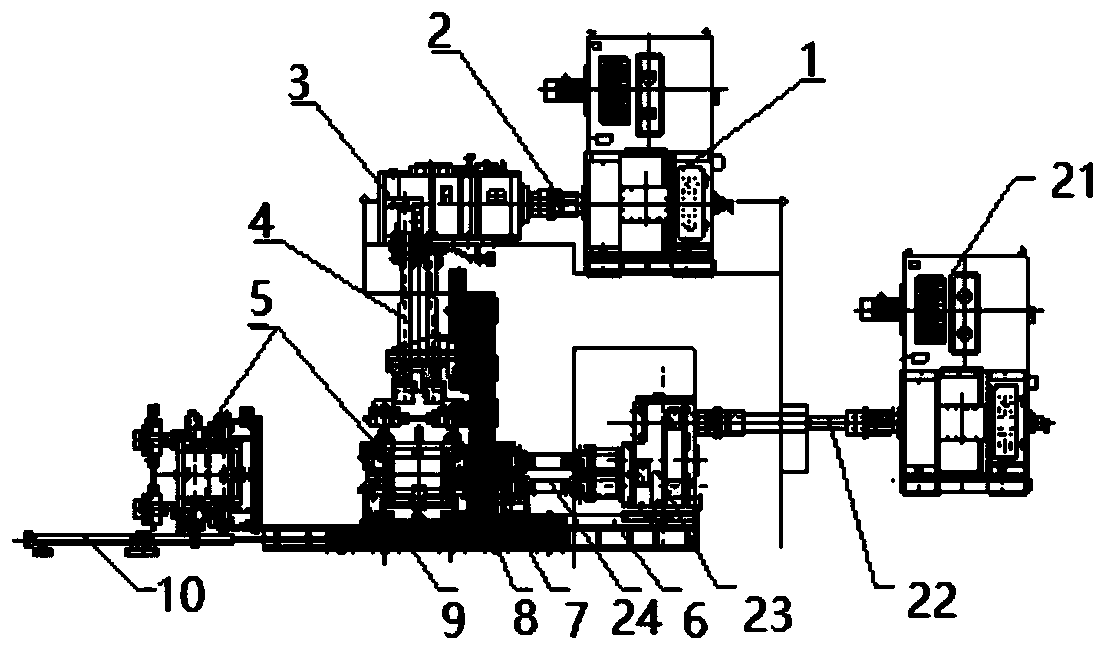
[0020] like figure 1 As shown, the rolling mill includes main motor one 1, main motor two 21, coupling one 2, coupling two 22, gearbox one 3, gearbox two 23, universal joint shaft one 4, universal joint shaft two 24. Rolling mill body 5, gearbox moving base 6, horizontal static base 7, pin hydraulic cylinder 8, vertical rolling mill roll changing trolley 9, and traverse hydraulic cylinder 10, of which, main motor 1, coupling 2, gear box One 3 and the universal joint shaft one 4 constitute a vertical rolling mill system, which is installed on the concrete platform foundation, and the vertical rolling mill system is connected to the rolling mill body 5 throug...


PUM


Abstract

The invention provides a horizontal and vertical switching rolling mill for bar finish rolling, and belongs to the technical field of bar rolling. The rolling mill comprises a vertical rolling mill system, a horizontal rolling mill system, a rolling mill body, a gear case movable base, a horizontal fixed base, a bolt hydraulic cylinder, a vertical rolling mill roller changing trolley and a transverse moving hydraulic cylinder. A vertical rolling mill transmission system is arranged on a concrete platform base and connected with the rolling mill body through a universal joint shaft. A rolling mill body movable base is arranged on a vertical fixed base, and the transverse moving hydraulic cylinder is connected with a horizontal rolling mill movable base and the vertical rolling mill roller changing trolley. A horizontal rolling mill transmission system is connected with the rolling mill body through a universal joint shaft, and is arranged on a horizontal fixed base through a movable base, and the bolt hydraulic cylinder is adopted for connecting the rolling mill movable base and the gear case movable base. The horizontal rolling mill series transmission system is integrated in a concrete platform base of a vertical rolling mill, and overhauling and installing are convenient; and the horizontal and vertical state switching time is short, and application is convenient.

Description

technical field [0001] The invention relates to the technical field of bar rolling, in particular to a horizontal-vertical switching rolling mill for bar finish rolling. Background technique [0002] In the prior art, there are generally three methods for rolling mill vertical conversion: [0003] (1) The Pomini type adopts two above-ground hydraulic cylinders to drive the steel structure frame with the rolling mill body to rotate 90° on the C-shaped frame to realize the horizontal rolling mill turning to the vertical state. The main motor passes through the bevel gearbox and the long shaft and the vertical The rolling mill transmission gearbox is connected, and the vertical state is driven by a main motor; (2) Danieli type uses an underground hydraulic cylinder to drive the steel structure frame with the rolling mill body to rotate 90° on the C-shaped frame to realize the horizontal rolling mill Turn to the vertical state, the main motor is connected with the transmission ...

Claims


Application Information

Patent Timeline
IPC IPC(8): B21B13/08B21B35/14B21B31/08
CPCB21B13/08B21B31/08B21B35/14
Inventor 程知松徐言东
Owner 北京科技大学设计研究院有限公司
Why Eureka
Try Eureka