Method and device for real-time thickness measurement and feedback of laser cladding

A laser cladding and thickness measurement technology, applied in measuring devices, metal material coating processes, instruments, etc., can solve the problems of difficult manual measurement, high cost of CCD cameras, inability to measure, etc., to improve cladding efficiency and processing. The effect of improving the qualified rate of finished products, improving the qualified rate of processed finished products, and reducing manual measurement errors

Active Publication Date: 2019-08-06
山东镭研激光科技有限公司
View PDF10 Cites 7 Cited by
  • Summary
  • Abstract
  • Description
  • Claims
  • Application Information

AI Technical Summary

Problems solved by technology

[0006] The measurement accuracy of the above-mentioned control technology is high, but laser cladding is a processing process that is affected by many factors such as laser power, powder, and matrix properties. In the actual complex industrial production environment, capturing the image of the molten pool will be interfered by many factors. It is easy to be blocked, and the temperature around the molten pool is high and there is a lot of dust, which also has high requirements for the long-term high-temperature stable operation of the CCD and the cleaning of the lens; in addition, the cost of the CCD camera is high, which increases the cost of equipment, and the calibration process is more complicated. , there are certain limitations

Method used


Image

  • Method and device for real-time thickness measurement and feedback of laser cladding
  • Method and device for real-time thickness measurement and feedback of laser cladding

Examples


Embodiment Construction

[0032] The present invention will be further described below in conjunction with specific embodiments.

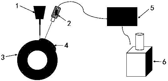
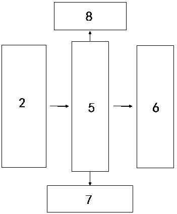
[0033] as attached figure 1 As shown, the device of the present invention includes a laser displacement sensor 2 and a controller 5. The laser displacement sensor 2 is installed near the laser processing head 1 and moves with it. The laser displacement sensor 2 measures that the laser is perpendicular to the laser cladding layer 4, which is Ensure that the measurement position is the low point of the laser cladding layer 4, and the measurement point is set on the same arc as the molten pool and close to the overlap of the two laser cladding layers 4.

[0034] Laser displacement sensor 2 is a diffuse reflection type digital display laser displacement sensor. Its main function is to measure height. Based on the principle of triangulation, it can radiate a laser line segment to the object, and receive diffuse reflection projection through the CMOS photosensitive element to obt...


PUM


Abstract

The invention relates to the technical field of laser cladding, and specifically discloses a method and a device for real-time thickness measurement and feedback of laser cladding. The method for real-time thickness measurement and feedback of laser cladding is characterized in that: a laser displacement sensor is installed near a laser processing head and driven along the laser processing head; the measurement laser of the laser displacement sensor is perpendicular to the laser cladding layer of a workpiece, and a measurement point of the measurement laser is arranged on the same arc as a molten pool and close to the joint of the two laser cladding layers; the laser displacement sensor is used for measuring the height of the cladding layer and feeding the measured value back to a controller; the controller finishes the value calculation, display and feedback, and then the controller controls the cladding parameters of the laser processing head, so that the final size meets the requirement. The method and device provided by the invention can adjust the laser processing parameters through the closed-loop control, control the thickness of the cladding layer precisely, reduce the manual measurement error, reduce the powder waste, and effectively improve the cladding efficiency and the qualified rate of the processed finished product.

Description

[0001] (1) Technical field [0002] The invention relates to the technical field of laser cladding, in particular to a real-time thickness measurement and feedback method and device for laser cladding. [0003] (2) Background technology [0004] Laser cladding, also known as laser cladding or laser cladding, is a new surface modification technology. It forms a metallurgically bonded cladding layer on the surface of the base by adding cladding materials to the surface of the substrate and using a high-energy-density laser beam to melt it together with the thin layer on the surface of the substrate. As a new surface treatment technology, laser cladding has been widely used in the field of engineering machinery manufacturing and remanufacturing. [0005] Regarding the application of laser cladding coating thickness measurement technology, the application number is 201810766782.8, and the patent name is "a laser cladding closed-loop control method based on stereo vision", which di...

Claims


Application Information

Patent Timeline
IPC IPC(8): C23C24/10G01D21/02
CPCC23C24/10G01D21/02
Inventor 何建群成巍吴明伟马庆增王文涛金硕刘森
Owner 山东镭研激光科技有限公司
Why Eureka
Try Eureka