Aluminum rod continuous casting and rolling production line

A continuous casting, continuous rolling, production line technology, applied in metal rolling, metal rolling, keeping the roll equipment in an effective state, etc., can solve the problems of reducing output, blocking rods, low production efficiency, etc., to avoid heat dissipation of aluminum alloy rods The effect of soot pollution

Inactive Publication Date: 2019-08-09
四川久勋科技有限公司
View PDF7 Cites 1 Cited by
  • Summary
  • Abstract
  • Description
  • Claims
  • Application Information

AI Technical Summary

Problems solved by technology

[0003] However, the traditional emulsion lubricated rolling mill is used in the continuous rolling process. During the rolling production process, the temperature of the rolled piece is relatively high, and water is required to cool the rolled piece during the rolling process.
The bearings and gears of rolling mills operate under high-speed and high-temperature conditions, and lubricating coolants are also required to lubricate and cool the bearings and gears. However, at present, the existing continuous rolling mills use emulsion to cool or During the rolling process, the emulsion is mixed with more impurities, mainly including solid particles, grease impurities, grease and emulsifiers, and insoluble impurities generated by calcium and magnesium ions in water, making the emulsion very Therefore, the use of emulsion to lubricate the bearings and gears of the continuous rolling mill will cause the bearings and gears to be damaged very quickly, and rod blocking and broken rod accidents often occur in the production process, forcing the production to be interrupted
Seriously affect the normal progress of production, reduce production, increase costs, and produce low efficiency

Method used


Image

  • Aluminum rod continuous casting and rolling production line
  • Aluminum rod continuous casting and rolling production line
  • Aluminum rod continuous casting and rolling production line

Examples


Embodiment 1

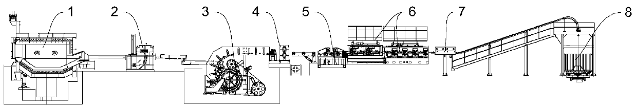
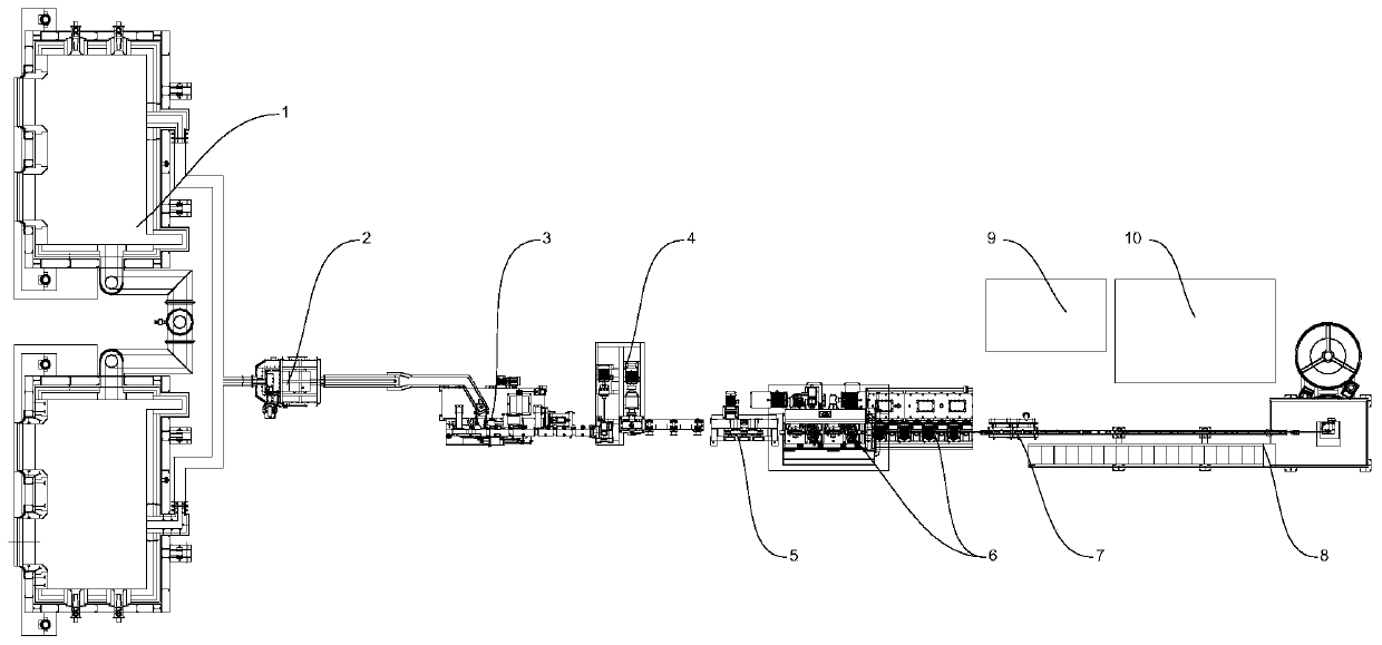
[0067] see Figure 1~2 , an aluminum rod continuous casting and rolling production line, including an aluminum furnace 1 for melting raw materials, a casting machine 3 for cooling and solidifying metal liquid, a rolling shear traction device 4 for pulling the casting machine 3 to form aluminum rods, for The continuous rolling mill 6 for aluminum rod rolling and forming, the wire take-up device 8 for taking up the wire, the wire take-up device 8 includes a wire winding device 87 for winding the rod wire, and the wire take-up device 8 also includes a take-up device for sliding the aluminum rod into The wire pipe 82 and the emulsion pipe 83 for transporting the emulsified cooling liquid are distributed with a plurality of guide milk blowing assemblies 84 on the wire take-up pipe 82, and the guide milk blow assembly 84 includes a guide wheel mounting seat 8401 arranged on the wire take-up pipe 82, The guide wheel mounting base 8401 is covered with a guide base seal cover 8402 for ...

Embodiment 2

[0080] The differences between this embodiment and Embodiment 1 mainly lie in: 1. The continuous rolling mill 6 in the production line is further improved.

[0081] see Figure 1~2 , an aluminum rod continuous casting and rolling production line, including an aluminum furnace 1 for melting raw materials, a casting machine 3 for cooling and solidifying metal liquid, a rolling shear traction device 4 for pulling the casting machine 3 to form aluminum rods, for The continuous rolling mill 6 for aluminum rod rolling and forming, the wire take-up device 8 for taking up the wire, the wire take-up device 8 includes a wire winding device 87 for winding the rod wire, and the wire take-up device 8 also includes a take-up device for sliding the aluminum rod into The line pipe 82 and the emulsion pipe 83 for conveying the emulsified cooling liquid are distributed with a plurality of guide milk blowing assemblies 84 on the line take-up pipe 82, and the guide milk blow assembly 84 includes ...

Embodiment 3

[0093] The difference between this embodiment and embodiment 2 is: 1) replace the continuous rolling mill, and replace the continuous rolling mill 6 independently driven by each rolling unit in embodiment 2 with a linked rolling mill 6; 2) add a roughing mill 11 before the continuous rolling mill .

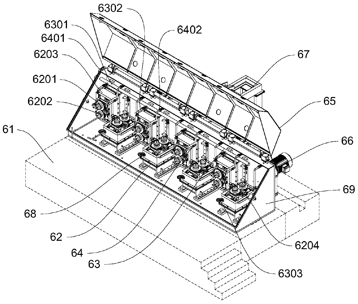
[0094] see Figures 16-19 , the linked rolling mill 6 and the continuous rolling mill of embodiment 2 all contain the rolling unit 602 and the system for cooling and lubricating. Drive concentrated continuous rolling unit 602, refer to Figure 20-21 , the horizontally arranged centralized continuous rolling unit 602 and the transmission linkage box 603 are driven through bevel gears for transmission and reversing, the vertically arranged centralized continuous rolling unit 602 and the transmission linkage box 603 are driven through direct connection for transmission, and the transmission parts of the above-mentioned centralized drive are arranged There are many ways, such as gea...


PUM


Abstract

The invention relates to the field of aluminum rod production rolling, in particular to an aluminum rod continuous casting and rolling production line. The aluminum rod continuous casting and rollingproduction line comprises an aluminum furnace used for melting a raw material, a casting machine used for cooling and solidifying molten metal, a roll shearing pulling device used for pulling an aluminum rod formed by the casting machine, a continuous rolling machine used for rolling forming of the aluminum rod, and a taking-up device used for taking up. The taking-up device does not use rod leading oil, and heat dissipating oil fume pollution of the aluminum alloy rod is avoided while it is ensured that the surface of the aluminum alloy rod is not scratched; and additionally, a lubricating oil and emulsion circulating system is arranged in the continuous rolling machine, lubricating oil lubricates and cools a bearing and a gear independently, an emulsion cools a rolled piece independently, thus abrasion caused by a traditional emulsion to the bearing and the gear is effectively avoided, the service lives of the bearing and the gear of the continuous rolling machine are prolonged, andthe accidents of rod blocking and breaking caused by quick aging and abrasion of the bearing and the gear in the production process are avoided.

Description

technical field [0001] The invention relates to the field of aluminum rod production and rolling, in particular to an aluminum rod continuous casting and rolling production line. Background technique [0002] At present, the production process of aluminum rod continuous casting and rolling is generally raw material→melting furnace→holding furnace→launder→pouring pot→casting machine→hydraulic shear→active feeding device→continuous rolling mill→rod closing device. [0003] However, the traditional emulsion lubricated rolling mill is used in the continuous rolling process. During the rolling production process, the temperature of the rolled piece is relatively high, and water is required to cool the rolled piece during the rolling process. The bearings and gears of rolling mills operate under high-speed and high-temperature conditions, and lubricating coolants are also required to lubricate and cool the bearings and gears. However, at present, the existing continuous rolling mi...

Claims


Application Information

Patent Timeline
Patent Type & Authority Applications(China)
IPC IPC(8): B21B1/46B21B15/00B21B45/02B21B28/00B21B39/16
CPCB21B1/46B21B15/00B21B28/00B21B39/165B21B45/0224B21B45/0281B21B2015/0057
Inventor 王吉成
Owner 四川久勋科技有限公司
Why Eureka
Try Eureka