
Mechanical processing method of wire arranging hole of large-size mold cavity board

A wiring hole and cavity technology, which is applied in the field of mechanical processing of wiring holes in large-scale combined welding cavity plates, can solve the problems of bottlenecks in production efficiency and process, and that the high-efficiency performance of CNC milling machines cannot be fully utilized.

Active Publication Date: 2019-08-09
CRRC CHANGCHUN RAILWAY VEHICLES CO LTD
View PDF8 Cites 3 Cited by
  • Summary
  • Abstract
  • Description
  • Claims
  • Application Information

AI Technical Summary

Problems solved by technology

[0017] In order to solve the hole opening operation process of the cavity floor of the existing rail passenger vehicle, it is necessary to carry out a large number of size surveying and error calculations on the overall large parts of the floor after the plug-in welding is completed. The actual Y-axis position of the welding seam M and the actual spacing value of the welding seam and its adjacent vertical bars can be calculated and determined together with the actual Y coordinate value of each vertical bar and its cumulative error offset, which can be used as the processing size The control parameters are used by the control system of the CNC milling machine; and in order to ensure the structural strength of the inclined rib plate and avoid the generation of bent and deformed oblique ribs, the existing process only uses the CNC milling machine to complete the milling operation of the upper panel, and the remaining large number of inclined ribs need to be removed. Ribs can only be removed by skilled operators using low-efficiency manual operations, which results in the high efficiency of CNC milling machines not being fully utilized in the process of threading cavity openings, and resulting in production efficiency being restricted by technological bottlenecks. The invention provides a machining method for opening a hole in a threading cavity

Method used


Image

  • Mechanical processing method of wire arranging hole of large-size mold cavity board
  • Mechanical processing method of wire arranging hole of large-size mold cavity board
  • Mechanical processing method of wire arranging hole of large-size mold cavity board

Examples


Embodiment Construction

[0078] The present invention will be further described in detail below in conjunction with the drawings.

[0079] Such as Figure 15 to Figure 20 As shown, the wiring hole machining method of the large-sized cavity plate of the present invention includes the following steps:

[0080] Step 1: The control system of the CNC milling machine determines whether the trapezoidal quadrangular prism clearing area of ​​the current wiring hole to be processed is a conventional trapezoidal quadrangular prism or a right-angled trapezoidal quadrangular prism according to the pre-inputted theoretical design parameters of the wiring hole drawing of the large cavity sheet It is: if the Y-direction theoretical coordinate value of the bottom and bottom of the trapezoid of the current wiring hole to be processed is equal to the theoretical Y coordinate value of the bottom and bottom of the trapezoid, or the Y-direction theoretical coordinate value of the bottom and proximal end of the trapezoid of the w...


PUM


Abstract

The invention provides a mechanical processing method of a wire arranging hole of a large-size mold cavity board, and belongs to the field of mechanical processing methods of wire arranging holes of large-size combined welding mold cavity boards. The method is a new method for re-determining core machining parameters of a trapezoidal removing area based on Y-direction coordinates of a central vertical surface of an acute-angle semicircular groove; the actual processing position parameters, re-determined based on the coordinates of the central vertical surface of an inherent acute-angle semicircular groove of the mold cavity board, of four boundary lines of a rectangle corresponding to the Z-direction lower end surface S of a general trapezoidal quadrangular removing area or the actual processing position parameters of four boundary lines of a rectangle corresponding to the Z-direction lower end surface S' of a right trapezoid quadrangular removing area are treated as new processing size control parameters of numerical control milling machine. Therefore, the side edges of a determined processing area avoid each vertical rib, and as a result, the vertical ribs are prevented from damage.

Description

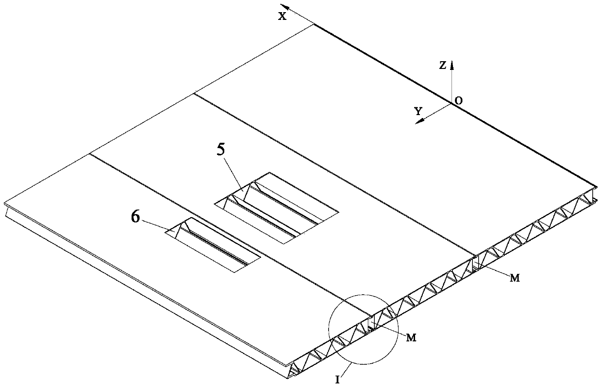
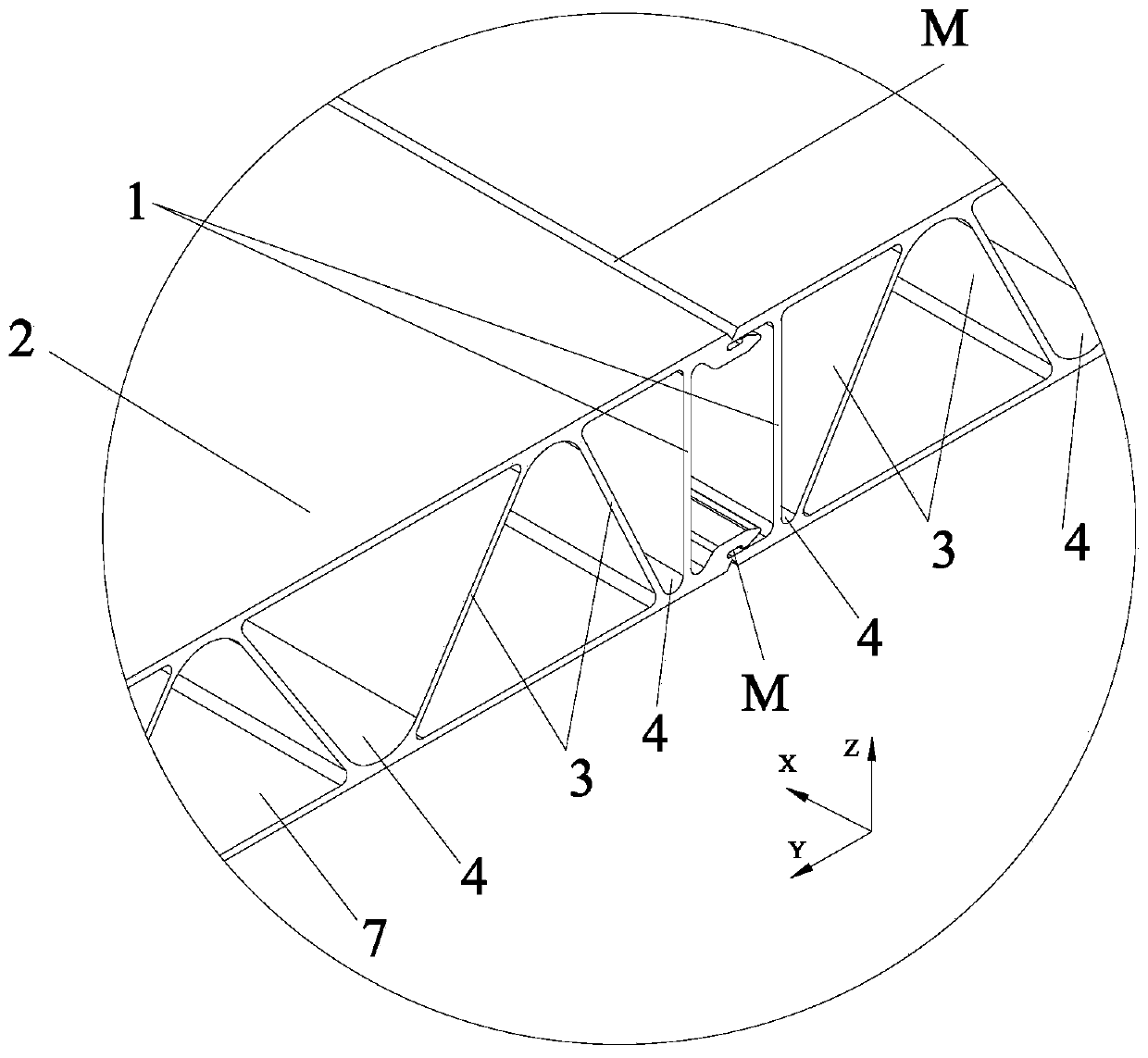
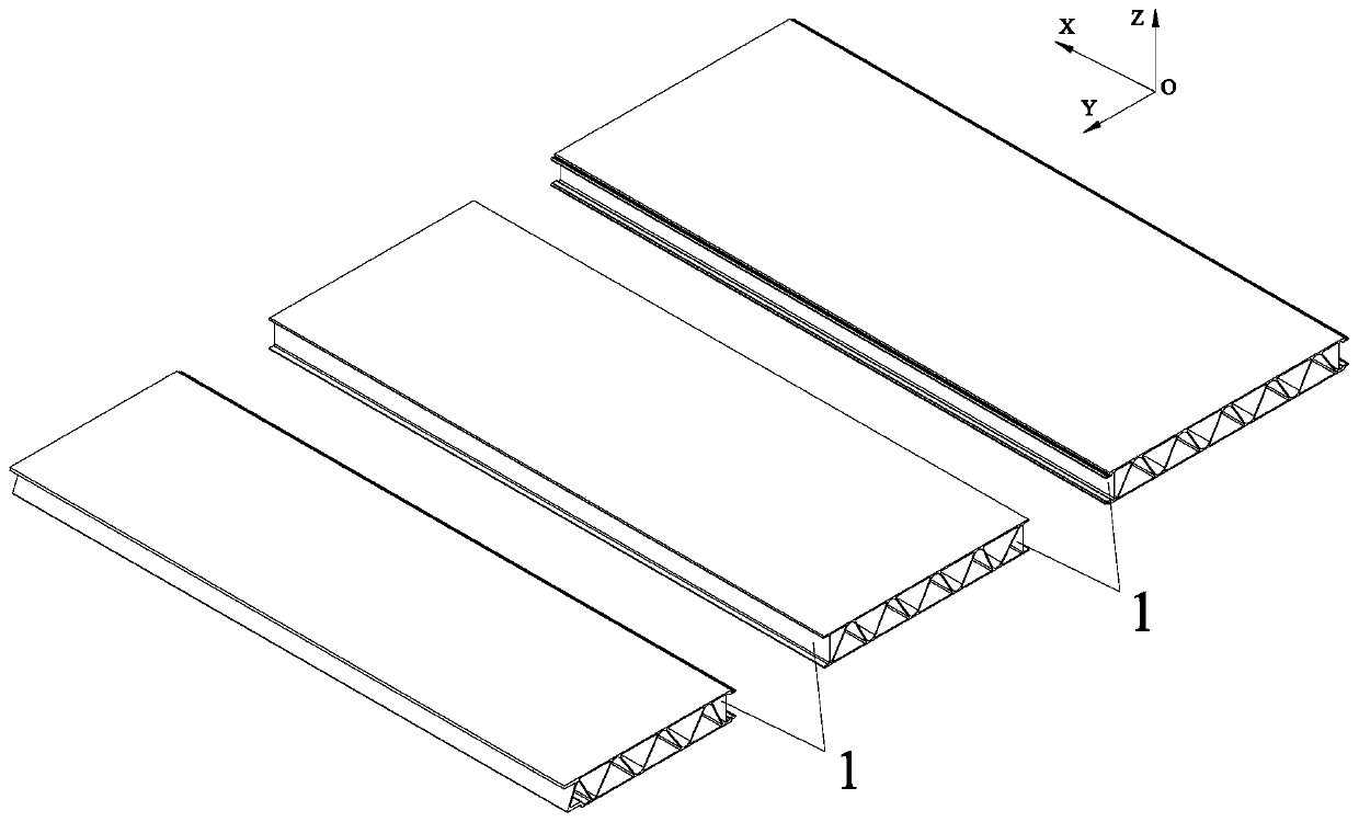
Technical field [0001] The invention belongs to the field of machining methods for wiring holes of large-scale combined welding cavity plates, and in particular relates to a method for machining wiring holes of large-scale cavity plates. Background technique [0002] The mid-vertical plane is a vertical plane passing through the central axis of the bottom surface of a geometric body, which refers to a section that can equally divide a symmetrical geometric body into two mirror-symmetrical parts along the vertical direction. Such as Figure 1 to Figure 3 As shown, the floor of the railway passenger car is a large integral part formed by the joint welding of multiple cavity plates, ( figure 1 In, only the left half of the large part of the floor is shown, and the right half is not shown in mirror symmetry with respect to the XOZ plane. Usually, the vertical plane of the large part of the floor is used as the reference plane of the XZ axis of the rectangular coordinate system. , And...

Claims


Application Information

Patent Timeline
IPC IPC(8): B23P15/00
CPCB23P15/00
Inventor 鲍洪阳田宇耿明李超
Owner CRRC CHANGCHUN RAILWAY VEHICLES CO LTD
Learn More