Cutter and tool bit structure thereof

A technology of cutter head and cutting edge, which is applied in the field of cutting tool and its cutter head structure, can solve the problems of difficult tool processing, short life and low processing efficiency, achieve low surface roughness, improve wear resistance, and improve processing efficiency Effect

Pending Publication Date: 2019-08-09
CONPROFE TECH GRP CO LTD +1
View PDF0 Cites 5 Cited by
  • Summary
  • Abstract
  • Description
  • Claims
  • Application Information

AI Technical Summary

Problems solved by technology

[0002] Graphite molds are more and more widely used due to their excellent thermal and electrical conductivity, lubricating properties and wear resistance, but graphite molds are not easy to process; at present, when it is necessary to semi-finish or finish machining curved surfaces on graphite molds, ordinary Although the flat bottom milling cutter mills the curved surface, although the processing efficiency is high, the remaining material steps are obvious, and the processing contour is poor; and the current milling cutter is usually coated with a wear-resistant coating on its surface in order to i

Method used


Image

  • Cutter and tool bit structure thereof
  • Cutter and tool bit structure thereof
  • Cutter and tool bit structure thereof

Examples


Embodiment 1

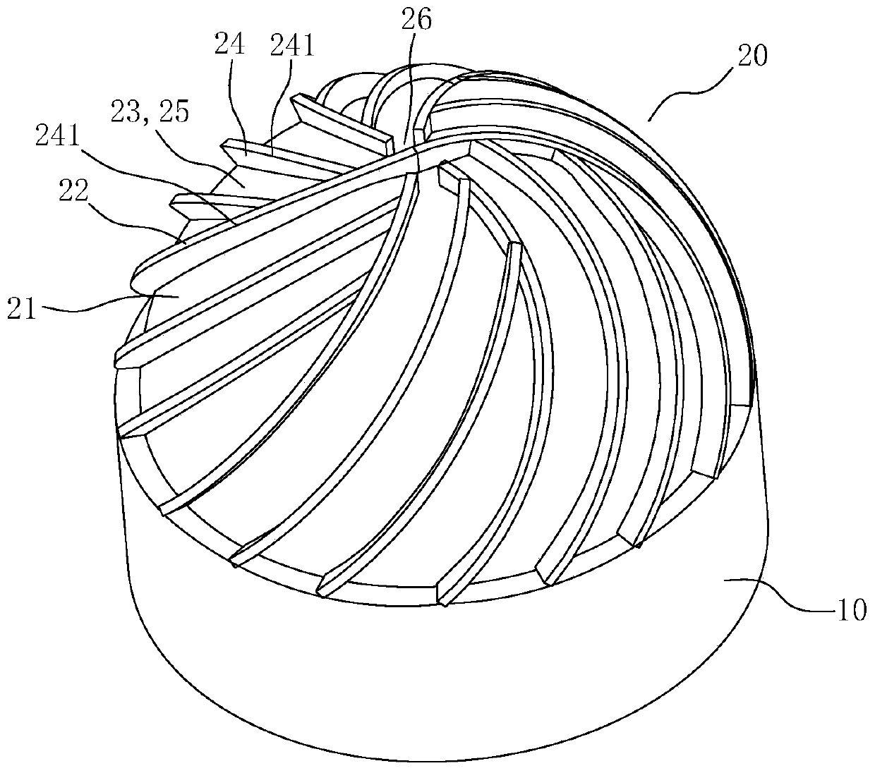
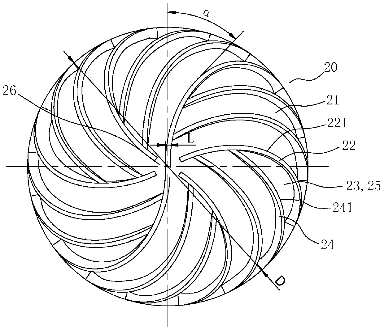
[0040] Such as Figure 1-Figure 3 As shown, the present embodiment provides a cutter head structure for a cutting tool, the cutter head structure includes a connecting portion 10 and a cutting edge portion 20 arranged at the front end of the connecting portion 10, and the cutting edge portion 20 includes a fixed The cutting main body 21 and several first cutting edges 22 at the front end of the connecting part 10, the outer surface of the cutting main body 21 is an outwardly convex arc surface, and the first cutting edge 22 is helical, and the first cutting edge The number of edges of 22 is defined as S, and the diameter of the cutting body 21 is defined as D. The following relationship must be satisfied between S and D: 4D≤S≤15D, that is, the number of edges S of the first cutting edge 22 is the diameter D of the cutting body 21 The diameter D of the cutting body 21 is 0.5-32 mm, and the width L of the first cutting edge 22 is 0.01 mm-0.1 mm.

[0041]The cutter head structur...

Embodiment 2

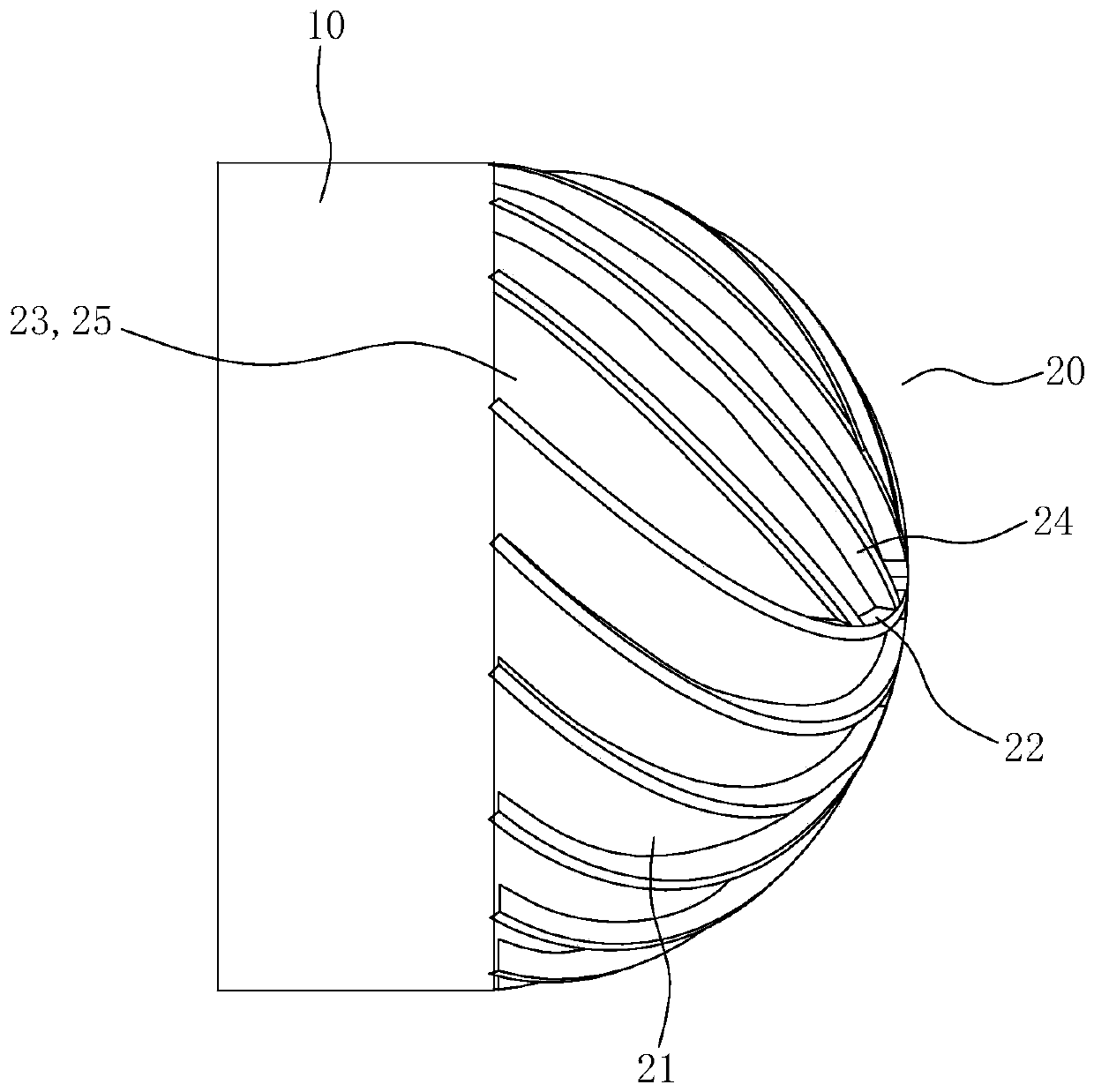
[0064] Please refer to the attached Figure 4 As shown, this embodiment provides another cutter head structure. The difference between this embodiment and Embodiment 1 is that one end of the first cutting edge 22 is set at the top area of ​​the cutting body 21, and the first The other end of the cutting edge 22 extends to the outer surface of the connecting portion 10; one end of the second cutting edge 24 is connected to the first cutting edge 22, and the other end of the second cutting edge 24 extends to the The outer surface of the connection part 10.

[0065] Compared with the first embodiment, the cutter head structure in this embodiment has a larger processing range.

[0066] For the same purpose, the second aspect of the embodiments of the present invention provides a cutting tool (not shown in the drawings), which includes a tool handle and a tool mounted on the front end of the tool handle as in any embodiment of the first aspect. The cutter head structure, the rear...


PUM

PropertyMeasurementUnit
Diameteraaaaaaaaaa
Blade widthaaaaaaaaaa
Surface roughnessaaaaaaaaaa

Abstract

The invention relates to the technical field of precise machining tools, and discloses a cutter and a tool bit structure thereof. The tool bit structure comprises a connecting part, and a cutting edgepart arranged at the front end of the connecting part; the cutting edge part comprises a cutting main body fixed at the front end of the connecting part, and multiple first cutting edges; the outer surface of the cutting main body is an arc surface projected outwards; the first cutting edges are spiral; the edge number S of the first cutting edges and the diameter D of the cutting main body meetthe relation of S not smaller than 4D and not larger than 15 D; the diameter D of the cutting main body is 0.5-32 mm; and the edge width L of the first cutting edges is 0.01-0.1 mm. The cutter has thefollowing benefits: the cutter is used for milling curved surfaces; under the same diameter, the edge distribution density is high, the surface roughness is excellent, and the machining efficiency ishigh; and when the cutter is applied to machine 3D glass graphite molds in a CNC, the surface roughness can reach 90 nm.

Description

technical field [0001] The invention relates to the technical field of precision machining tools, in particular to a cutting tool and its cutter head structure. Background technique [0002] Graphite molds are more and more widely used due to their excellent thermal and electrical conductivity, lubricating properties and wear resistance, but graphite molds are not easy to process; at present, when it is necessary to semi-finish or finish machining curved surfaces on graphite molds, ordinary Although the flat bottom milling cutter mills the curved surface, although the processing efficiency is high, the remaining material steps are obvious, and the processing contour is poor; and the current milling cutter is usually coated with a wear-resistant coating on its surface in order to increase its wear resistance. layer (such as WC, diamond, etc.), the processing of the tool is difficult and the life is short, and the roughness and uniformity of the workpiece surface formed by the...

Claims


Application Information

Patent Timeline
IPC IPC(8): B28D1/18B28D5/02B23P15/34
CPCB23P15/34B28D1/186B28D5/02
Inventor 颜炳姜李伟秋
Owner CONPROFE TECH GRP CO LTD
Why Eureka
Try Eureka