Bipolar plate, fuel cell stack comprising same, and power generation system

A fuel cell stack and bipolar plate technology, which is applied in the direction of fuel cells, power system fuel cells, fuel cell components, etc., can solve the problems of unfavorable reaction product water discharge, parasitic power increase, poor drainage, etc. , to achieve the effects of easy control, reduced parasitic power, and favorable voltage drop

Inactive Publication Date: 2019-08-09
张国胜 +1
View PDF0 Cites 4 Cited by
  • Summary
  • Abstract
  • Description
  • Claims
  • Application Information

AI Technical Summary

Problems solved by technology

The straight-through flow channel has a simple structure and low flow resistance, but the power generated by the fuel cell stack is sensitive to fluctuations in gas pressure
The pressure drop of multiple parallel serpentine flow channels is large, which facilitates the diffusion of gas to the gas diffusion layer and the electrode catalyst. However, if the serpentine flow channels are used on the cathode side of the PEMFC, it is not conducive to the discharge of the reaction product water.
In the prior art, the fuel flow channel on the anode plate and the oxidant flow channel on the cathode plate often adopt the same pattern, either as a serpentine flow channel or as a straight-through flow channel. It is difficult to adjust the pressure drop and the pressure drop of air (or oxygen) to the optimum value at the same time, because the fluidity of hydrogen is better than that of air and oxygen. When the pressure drop of hydrogen reaches the optimum value on the anode side of the PEMFC, The pressure drop of air or oxygen on the cathode side of the PEMFC will inevitably be too large, which will lead to increased parasitic power and poor drainage

Method used


Image

  • Bipolar plate, fuel cell stack comprising same, and power generation system
  • Bipolar plate, fuel cell stack comprising same, and power generation system
  • Bipolar plate, fuel cell stack comprising same, and power generation system

Examples


Embodiment 1

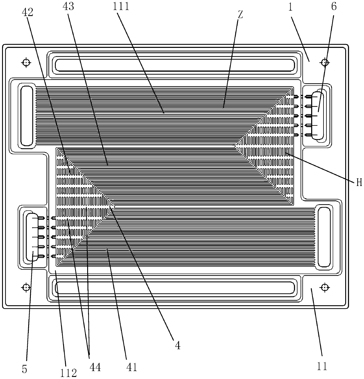
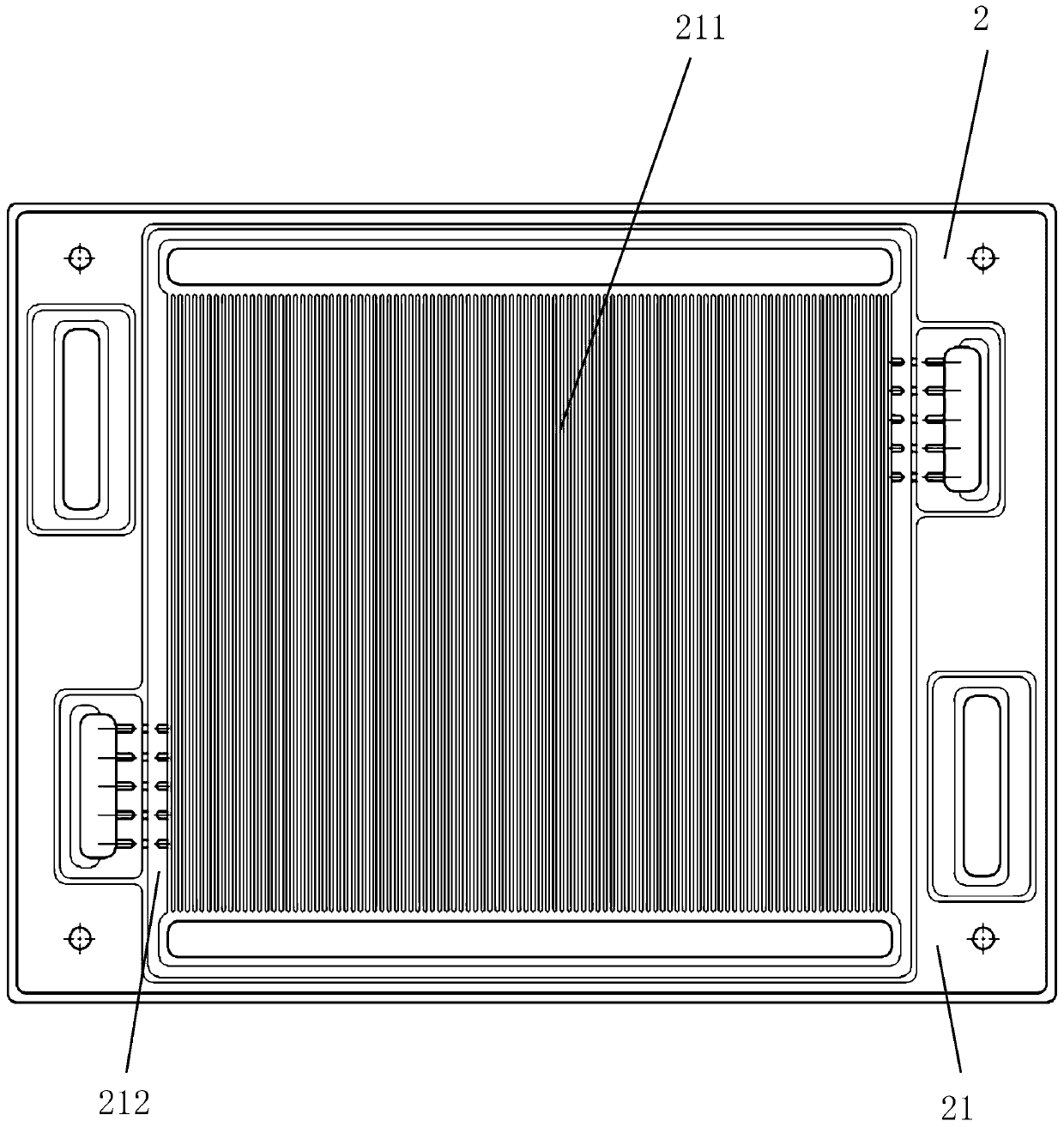
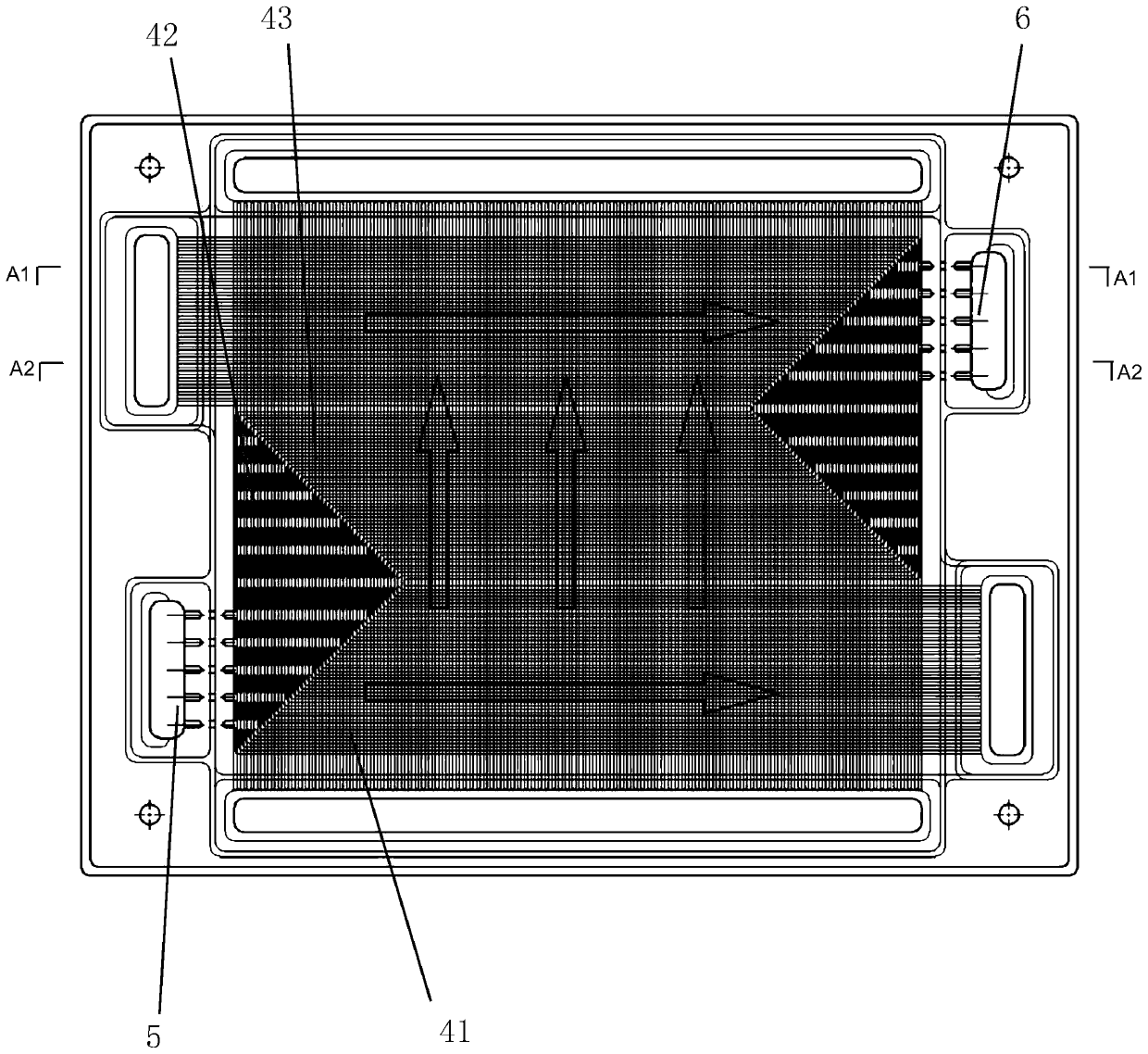
[0055] Such as Figure 1-Figure 3 As shown, the present invention provides a bipolar plate, which is the first embodiment of the present invention, and includes a first plate 1 and a second plate 2. The first plate 1 has a first surface 11 and a second surface 12. , The second electrode plate 2 has a third surface 21 and a fourth surface 22, the second surface 12 of the first electrode plate 1 and the fourth surface 22 of the second electrode plate 2 are bonded together, forming a Coolant runner 3. The first surface 11 of the first electrode plate 1 has a first flow channel 111 and a first reference surface 112, and the second surface 12 has a second flow channel 121 and a second reference surface 122. The third surface 21 of the second electrode plate 2 has a third flow channel 211 and a third reference surface 212, and the fourth surface 22 has a fourth flow channel 221 and a fourth reference surface 222. The first flow passage 111 is a groove formed in the thickness directi...


PUM

PropertyMeasurementUnit
thicknessaaaaaaaaaa

Abstract

The invention discloses a bipolar plate, a fuel cell stack comprising the same, and a power generation system. The bipolar plate includes a first polar plate and a second polar plate, wherein the first polar plate has a first face and a second face, and the second polar plate has a third face and a fourth face. The first face of the first polar plate has a first flow channel and a first referenceface, and the third surface of the second polar plate is provided with a third runner and a third reference surface. In the bipolar plate, the second surface of the first polar plate is attached to the fourth surface of the second polar plate, and the first surface of the first polar plate and the third surface of the second polar plate have different flow fields. The bipolar plate also comprisesat least two synchronous fluctuating areas which are channels for leading a cooling agent in and out of a bipolar plate interlayer. A cooling agent guide dike is arranged on the second polar plate andcan guide the cooling agent to flow according to a set route. Due to the characteristics, the bipolar plate has the advantages of good drainage performance, good cooling effect and the like.

Description

Technical field [0001] The invention belongs to the technical field of fuel cells, and particularly relates to a bipolar plate used in a fuel cell stack, and a fuel cell stack and a power generation system containing the bipolar plate. Background technique [0002] Fuel cell is an electrochemical reaction device that can convert chemical energy into electrical energy. It has the advantages of high energy conversion efficiency, zero emission, and no mechanical noise. It is favored in military and civilian fields. Proton exchange membrane fuel cells (PEMFC) use solid polymer membranes as electrolytes, which have the advantages of simple structure and low operating temperature, and have unique advantages as a mobile power source. Internationally renowned automobile companies such as Toyota Motor Corporation of Japan and Hyundai Motor Corporation of South Korea have developed mass-produced fuel cell electric vehicles (FCEV or FCV) powered by PEMFC. [0003] Each PEMFC cell consists of...

Claims


Application Information

Patent Timeline
Patent Type & Authority Applications(China)
IPC IPC(8): H01M8/0258H01M8/0263H01M8/0267
CPCH01M8/0258H01M8/0263H01M8/0267Y02E60/50H01M8/026H01M2250/20
Inventor 张国胜张知劲
Owner 张国胜
Why Eureka
Try Eureka