Control method for single-phase three-level NPC rectifier of motor train unit based on super-twisting sliding mode
A control method and super-helical technology, applied to electrical components, AC power input conversion to DC power output, output power conversion devices, etc., to achieve the effects of harmonic content reduction, chattering control, and enhanced robustness
- Summary
- Abstract
- Description
- Claims
- Application Information
AI Technical Summary
Problems solved by technology
Method used
Image


Examples
Embodiment 1
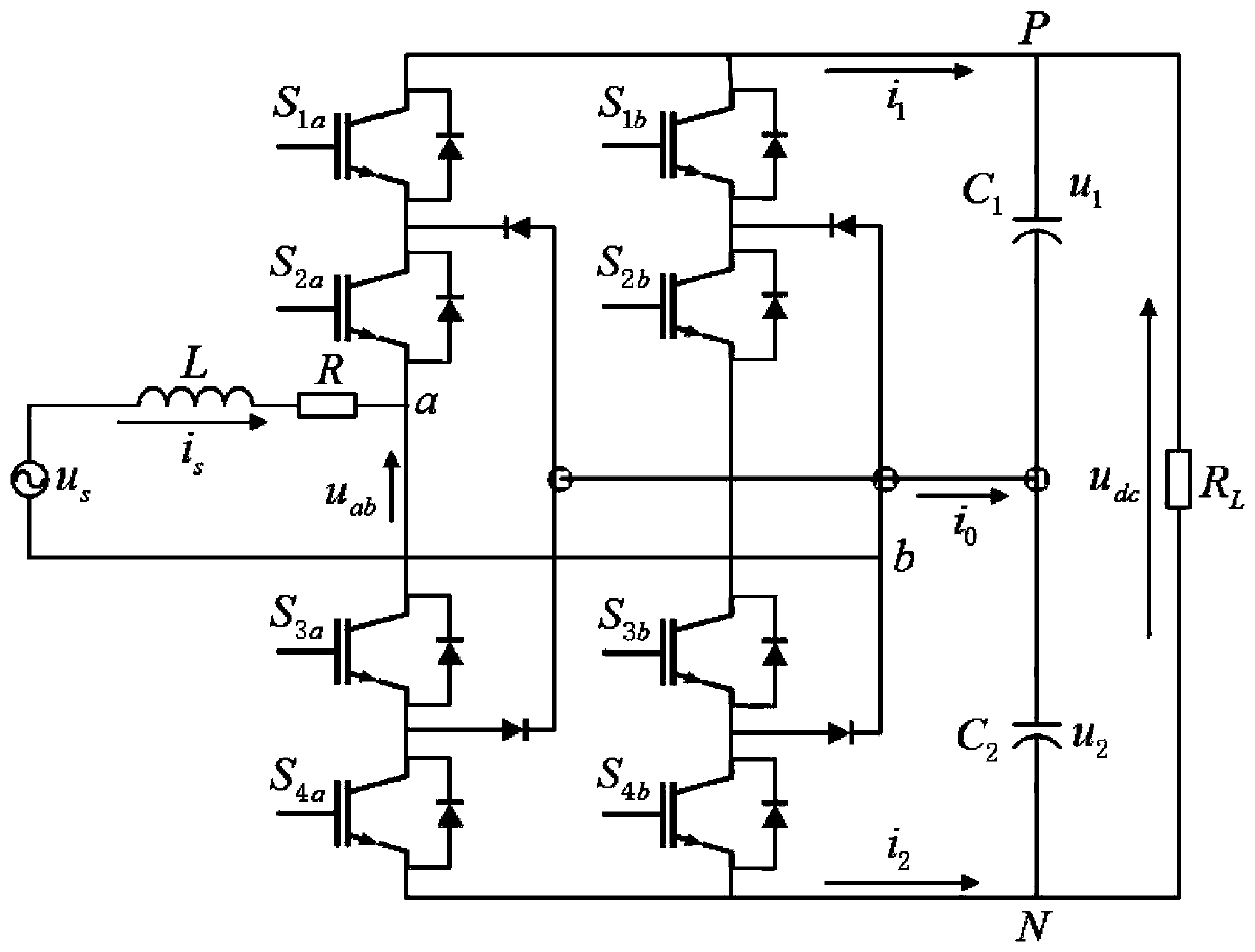
[0065] The topology of the traction system rectifier is as follows figure 1 shown. u s The grid-side voltage of the rectifier output through the on-board transformer; R and L are the equivalent resistance and inductance of the on-board traction transformer respectively; the DC side capacitance is shown as C 1 and C 2 ; L is the equivalent resistance of the system load; for the convenience of analysis, first define the switch in the rectifier as an ideal switch, as:
[0066]
[0067] where i=a,b.
[0068] According to formula (1), the nine switching modes and corresponding voltage values of the main circuit can be expressed as shown in Table 1.
[0069] Table 1 Working mode of NPC rectifier
[0070]
[0071] by right figure 1 The main circuit in is analyzed using Kirchhoff's law, and the mathematical model of the circuit can be obtained:
[0072]
[0073]
[0074] Introducing the d-q transformation idea of the three-phase rectifier into the single-phase ...
Embodiment 2
[0111] In order to verify the feasibility of the designed control algorithm, the two working conditions of the system when the traction starts and the traction load changes are simulated, the stability of the DC side output voltage, the robustness of the DC side voltage and the harmonic characteristics of the AC side input current Perform simulation analysis. The parameter settings used in the simulation are shown in Table 2.
[0112] Table 2 Simulation parameters
[0113]
[0114] The traction working condition refers to the state of the system from connecting the load to running at a constant speed. By comparing the time for the system to reach a steady state, the harmonic content of the input current at the grid side, and the voltage fluctuation data under the two different control methods, the control system is finally verified. The superiority of the method.
[0115] In the initial stage, the system is connected to the load R=7Ω. It can be seen from the figure that a...
PUM
 Abstract
Description
Claims
Application Information
 - R&D
- Intellectual Property
- Life Sciences
- Materials
- Tech Scout
- Unparalleled Data Quality
- Higher Quality Content
- 60% Fewer Hallucinations
Browse by: Latest US Patents, China's latest patents, Technical Efficacy Thesaurus, Application Domain, Technology Topic, Popular Technical Reports.
© 2025 PatSnap. All rights reserved.Legal|Privacy policy|Modern Slavery Act Transparency Statement|Sitemap|About US| Contact US: help@patsnap.com