Axisymmetric gas-solid coupling heat transfer model, analysis method and application system
A heat transfer model and analysis method technology, applied in the field of solid heat transfer finite element method analysis, can solve problems such as inability to accurately analyze gas temperature changes, reducing accuracy, and error in component life estimates.
- Summary
- Abstract
- Description
- Claims
- Application Information
AI Technical Summary
Problems solved by technology
Method used
Image
Examples
Embodiment 1
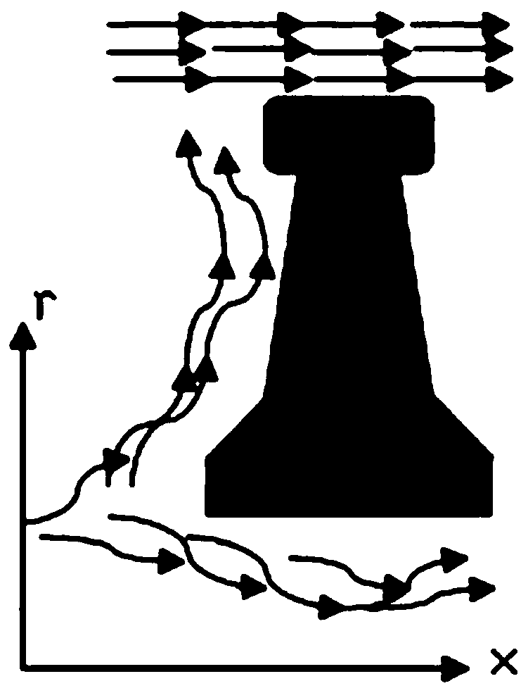
[0056] This embodiment takes figure 1 The turbine disk of the aero-engine shown is taken as an example to illustrate the difference between the axisymmetric gas-solid coupling heat transfer model proposed by the present invention and the traditional heat transfer analysis model. figure 1 The axisymmetric section indicated by the circle, such as figure 2 shown.
[0057] Such as figure 2 As shown, in this embodiment, the fluid (including cooling gas and gas) performs convective heat exchange on the boundary of the turbine disk; wherein, the straight arrows represent the gas flow direction, and the random curved arrows represent the cooling gas flow direction.
[0058] The thermal load borne by an aeroengine during its operation has the characteristics of spatial distribution and time variation, forming a physical field problem of initial boundary value. The heat transfer mode inside the turbine disk (solid) is heat conduction, and its heat transfer control equation is as fo...
Embodiment 2
[0108] This embodiment specifically illustrates how to apply the gas-solid coupling heat transfer model described in Embodiment 1 considering the gas temperature change at the gas-solid boundary to obtain all solid node temperatures and gas node temperatures.
[0109] The calculation process for obtaining all solid node temperatures and gas node temperatures of solids is as follows: Figure 6 As shown, it specifically includes the following steps:
[0110] Step 1. Selecting and intercepting an axisymmetric plane of the solid to obtain a two-dimensional geometric model of the plane;
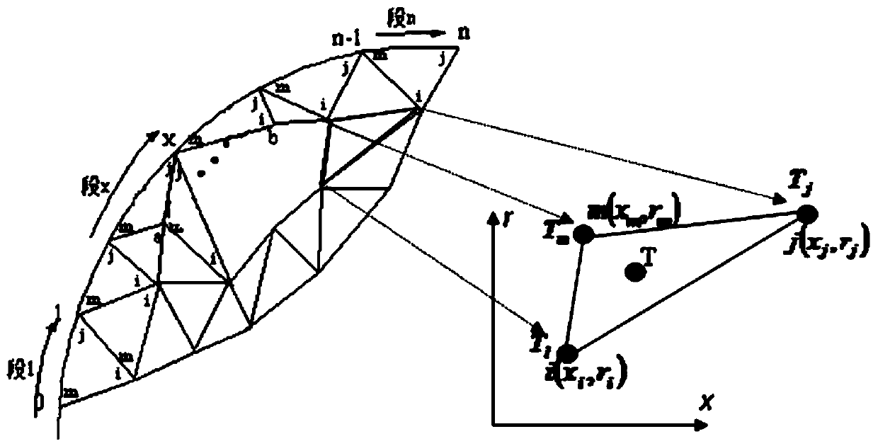
[0111] Step 2, generating a triangular mesh on the semi-meridian plane of the two-dimensional geometric model;
[0112] Step 3, establishing a finite element triangular classical heat transfer model inside the solid;
[0113] Step 4, setting up the heat transfer model of the gas-solid boundary triangular unit as described in any of claims 1-6;
[0114] Step 5, based on the results of the step 3...
Embodiment 3
[0121] In order to apply Embodiment 1 or Embodiment 2 to specific projects, this embodiment also designs such Figure 7 The application system shown includes geometric modeling subsystem, grid division subsystem and gas-solid coupling analysis subsystem. The geometric modeling subsystem receives a given solid computer model in the CAD system, and performs detail feature processing; the mesh division subsystem obtains the finite element triangular mesh of the solid based on the processing results of the geometric modeling subsystem , and transmitted to the gas-solid coupling analysis subsystem; the gas-solid coupling analysis subsystem establishes the internal finite element triangular classical heat transfer model of the solid and the gas-solid coupling heat transfer model of the gas-solid boundary, and calculates the Solid all solid node temperatures and gas boundary node temperature values; the CAD system can be UG system, AutoCAD system or SolidWorks system.
PUM
 Abstract
Description
Claims
Application Information
 - R&D
- Intellectual Property
- Life Sciences
- Materials
- Tech Scout
- Unparalleled Data Quality
- Higher Quality Content
- 60% Fewer Hallucinations
Browse by: Latest US Patents, China's latest patents, Technical Efficacy Thesaurus, Application Domain, Technology Topic, Popular Technical Reports.
© 2025 PatSnap. All rights reserved.Legal|Privacy policy|Modern Slavery Act Transparency Statement|Sitemap|About US| Contact US: help@patsnap.com


