
A new type of longitudinal magnetic contact system with built-in magnetic gathering ring and reverse contact cup

A technology of contact system and magnetic ring, which is applied in high-voltage/high-current switches, high-voltage air circuit breakers, electrical components, etc., can solve the problems of reducing the recovery speed of medium strength, successfully breaking unfavorable currents, and insufficient breaking capacity. , to achieve the effects of control, improvement of magnetic field distribution characteristics, and rapid recovery of dielectric strength

Active Publication Date: 2021-06-04
SICHUAN UNIV
View PDF5 Cites 0 Cited by
  • Summary
  • Abstract
  • Description
  • Claims
  • Application Information

AI Technical Summary

Problems solved by technology

However, the residual longitudinal magnetic field in the center of the contact of the traditional cup-shaped longitudinal magnetic contact system is relatively large, which will prevent the diffusion of residual plasma in the contact gap, reduce the recovery speed of the dielectric strength, and is not conducive to the successful breaking of the current
At the same time, the traditional cup-shaped longitudinal magnetic contact system has low mechanical strength, weak magnetic field strength, and insufficient breaking capacity, so it is not suitable for large-capacity vacuum interrupters

Method used


Image

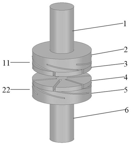
  • A new type of longitudinal magnetic contact system with built-in magnetic gathering ring and reverse contact cup
  • A new type of longitudinal magnetic contact system with built-in magnetic gathering ring and reverse contact cup
  • A new type of longitudinal magnetic contact system with built-in magnetic gathering ring and reverse contact cup

Examples


Embodiment Construction

[0017] The present invention proposes a novel contact system with a built-in magnetic gathering ring and a reverse contact cup. The present invention will be further described below in conjunction with the accompanying drawings.

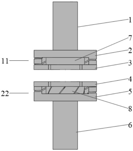
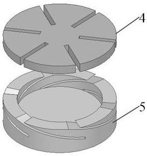
[0018] Such as figure 1 , 2 As shown, the overall structure of the new longitudinal magnetic contact system includes: dynamic and static side contact combination structures 11, 22; the static side contact combination structure includes static conductive rod 1, external static contact cup 2, embedded magnetic The ring 7 and the contact piece 3 ; the combined structure of the moving side contact includes a moving conductive rod 6 , an outer moving contact cup 5 , a contact piece 4 and an embedded reverse contact cup 8 . Wherein, the dynamic and static conductive rods 6, 1 are coaxially connected to the tops of the external contact cups 5, 2, respectively, and the contact pieces 4, 3 are coaxially connected to the bottoms of the external contact cups 5...


PUM


Abstract

The present invention designs a novel longitudinal magnetic contact system with a built-in magnetic gathering ring and a reverse contact cup, which consists of a conductive rod, an external contact cup, a contact piece, a built-in magnetic gathering ring and a built-in reverse contact cup. The embedded magnetic gathering ring is coaxially connected with the external static contact cup and the contact piece; the wall of the embedded reverse contact cup is provided with a spiral groove opposite to the direction of the external contact cup, which is connected with the external dynamic contact cup. The contact cup and the contact piece are coaxially closely connected. The new longitudinal magnetic contact system through the introduction of the magnetic gathering ring and the reverse contact cup and the optimized design of the contact structure, on the basis of increasing the longitudinal magnetic field at the peak time of the contact gap current, it effectively weakens the remaining longitudinal magnetic field in the center of the contact. The magnetic field reduces the influence of residual magnetism on the diffusion of residual plasma, which is beneficial to the recovery of the dielectric strength of the contact gap after arcing and the improvement of the breaking capacity of the contact. In addition, the newly designed contact system has a simple structure, is easy to assemble, and has high mechanical strength, which is conducive to popularization and application in actual production.

Description

technical field [0001] The invention relates to a novel longitudinal magnetic contact system of a vacuum interrupter with a built-in magnetic gathering ring and a reverse contact cup. Background technique [0002] Circuit breakers play dual roles of protection and control in power systems, and their breaking performance is very important. Vacuum circuit breakers, which use vacuum as the insulation and arc-extinguishing medium, occupy an absolute dominant position in the medium-voltage field of power systems due to their excellent performance, and are currently developing towards high-voltage and high-current. During the breaking process of the vacuum circuit breaker, the contact material evaporates and ionizes to form a vacuum arc plasma. The vacuum arc will produce an obvious contraction effect under the action of the strong magnetic pinch force of the self-generated magnetic field, which will cause severe ablation on the contact surface, and A large amount of metal vapor ...

Claims


Application Information

Patent Timeline
Patent Type & Authority Patents(China)
IPC IPC(8): H01H33/664
CPCH01H33/6642
Inventor 黄小龙苏芳菲白雪艳闫志强王泽龙杨梦洁赵莉华任俊文吴迅张振东
Owner SICHUAN UNIV
Learn More