Automatic forming machine for supporting frame

A technology of automatic forming machine and support frame, which is applied to other household appliances, household appliances, applications, etc., can solve the problems of insufficient bending accuracy, uneven deformation of steel wires, waste of time and labor, etc., and achieve reduction Work load, increase production efficiency and molding effect, and effect of reasonable structure

Inactive Publication Date: 2019-08-16
徐州奔蓝机械科技有限公司
View PDF0 Cites 0 Cited by
  • Summary
  • Abstract
  • Description
  • Claims
  • Application Information

AI Technical Summary

Problems solved by technology

A support frame of a foldable clothes hanger is rolled from steel wire rods. In traditional production, it is processed manually with the help of machines through three and a half manual processes. The first process uses a two-way crimping machine to meet the requirements. The middle part of the wire rod of the same size is bent on both sides to form a "U"-shaped opening structure; the second step is to manually bend the corners on both sides of the wire rod to 90 degrees inward with the help of punching machine equipment; the third step is to manually bend the wire rod on the " The ends of both sides of the U" shape are hooked outward; forming a steel support frame with bilateral symmetry. In mass production, manual bending is usually used, which will result in slow efficiency and different lengths of the produced lines, making steel The deformation of the wire rod is uneven during manual processing, and there is a large internal stress inside it. The bending accuracy cannot meet the requirements. Multiple process adjustments waste time and labor, and increase labor intensity.

Method used


Image

  • Automatic forming machine for supporting frame
  • Automatic forming machine for supporting frame
  • Automatic forming machine for supporting frame

Examples


Embodiment Construction

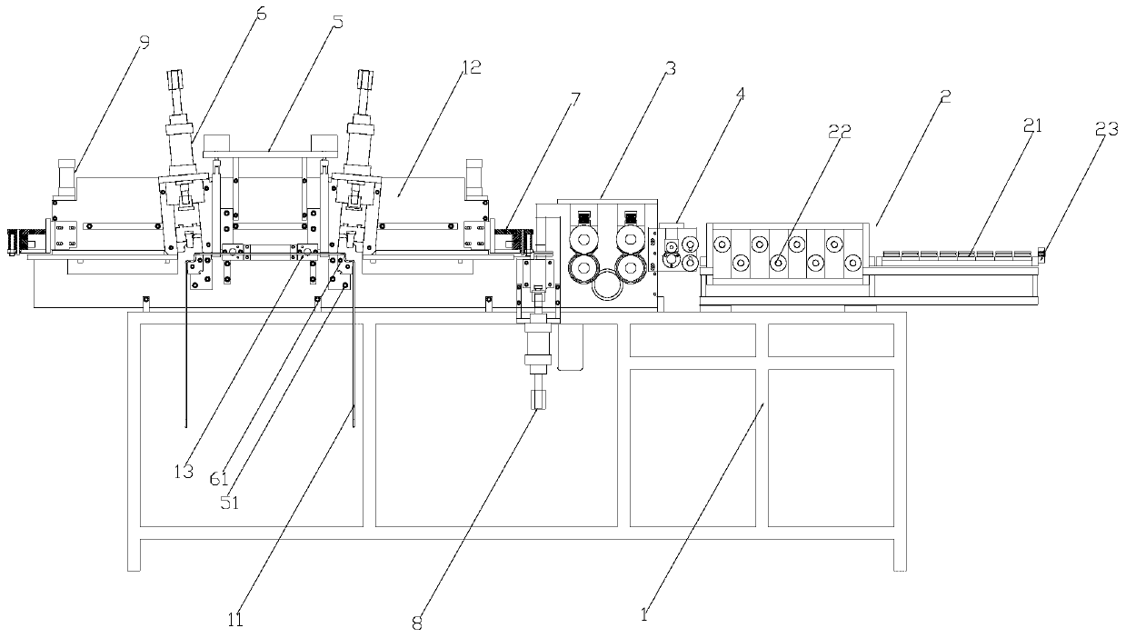
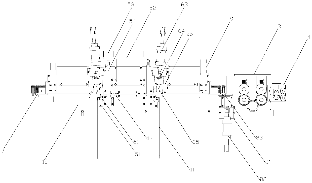
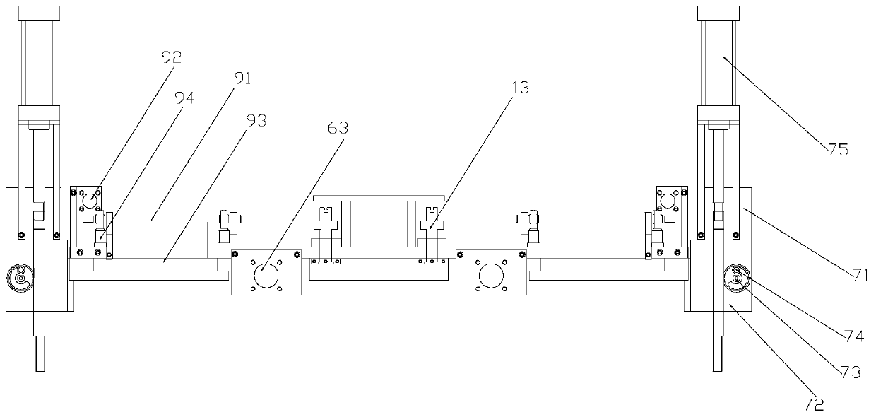
[0021] Such as Figure 1-Figure 4 As shown, the automatic molding machine of the support frame of the present invention includes a frame 1, and one end of the working surface of the frame 1 is provided with a wire adjustment mechanism 2 that straightens and flattens the wire 11, the wire adjustment The mechanism 2 includes a horizontal pressing wheel group 21 and a longitudinal pressing wheel group 22. The horizontal pressing wheel group 21 and the longitudinal pressing wheel group 22 are on the same horizontal plane. The inlet end of the horizontal pressing wheel group 21 A wire nozzle 23 is provided. The wire outlet side of the wire adjusting mechanism 2 is installed on the working surface of the frame 1 with a wire wire mechanism 3 for conveying the wire 11, and the wire mechanism 3 is provided with a wire pressing outlet with the longitudinal pressing wheel group 22 In the wire pulley group 31 on the same horizontal plane, the wire pulley 31 and the operating table 12 are o...


PUM


Abstract

The invention belongs to the technical field of wire rolling equipment, and particularly relates to an automatic forming machine for a supporting frame. The automatic forming machine comprises a rack,a wire adjusting mechanism for straightening and flattening a wire is arranged at one end of the work face of the rack, and a wire guide mechanism for conveying the wire is mounted at the position, on the work face of the rack, of the wire-out side of the wire adjusting mechanism. A vertical operation table is mounted at the position, on the work face of the rack, of the wire-out side of the wireguide mechanism, a wire supporting seat for containing the wire conveyed out by the wire-out side of the wire guide mechanism is arranged in the middle of the operation table, a compressing mechanismfor fixing the wire in cooperation with the wire supporting seat is mounted at the position, above the wire supporting seat, of the operation table, rolling mechanisms for rolling the wire are mounted at the positions, located on the operation table, of the two sides of the compressing mechanism, and hook rolling mechanisms for press-bending the end of the wire are mounted at the positions, located on the operation table, of the two sides of the rolling mechanisms. According to the automatic forming machine, the production efficiency and forming effect of the supporting frame are improved, the structure is reasonable, the automation level is high, the forming quality is high, and the automatic forming machine is beneficial to being popularized and applied in the clothes hanger processingmarket.

Description

Technical field [0001] The invention belongs to the technical field of wire rod rolling equipment, in particular to an automatic forming machine of a support frame. Background technique [0002] With the continuous development of industrial automation in today's society, automated production lines play an important role in the industry, and the requirements for automation in mass production of products are extremely high. The support frame of a foldable drying rack is made by rolling steel wire rod. In traditional production, it is processed manually through three semi-manual processes with the help of a machine. The first one uses a two-way crimping machine to meet the requirements. The middle part of the wire of the size is bent on both sides into a "U"-shaped opening structure; the second manual use of the punching machine equipment to roll the corners on both sides of the wire 90 degrees inward; the third manual use of the equipment The U”-shaped two ends are rolled to the o...

Claims


Application Information

Patent Timeline
Patent Type & Authority Applications(China)
IPC IPC(8): B21F45/02
CPCB21F45/02
Inventor 陈良旺
Owner 徐州奔蓝机械科技有限公司
Why Eureka
Try Eureka