

Laser welding control method, device, system and electronic device
A technology of laser welding and control method, applied in laser welding equipment, welding equipment, welding equipment and other directions, can solve the problems of blast hole welding, welding accumulation, collapse, etc., and achieve the goal of welding, the device is neat, the welding is uniform, and the jitter is reduced. Effect
- Summary
- Abstract
- Description
- Claims
- Application Information
AI Technical Summary
Problems solved by technology
Method used
Image

Examples
Embodiment 1
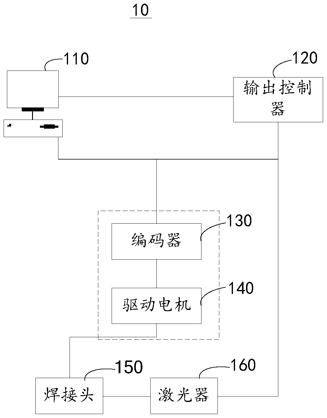
[0066] Such as figure 1 As shown, it is a schematic diagram of interaction of the laser welding control system 10 provided in the embodiment of the present application. The laser welding control system 10 includes a controller, an encoder 130 , a driving motor 140 , a welding head 150 and a laser 160 .
[0067] The aforementioned controllers may include a main controller 110 and an output controller 120 .
[0068] The main controller 110 is connected with the laser 160 and the encoder 130 , and is used to output the welding track of the target device to be welded to the encoder 130 .
[0069] The above-mentioned main controller 110 may be a network server, a database server, or a personal computer (personal computer, PC), a tablet computer, a smart phone, a personal digital assistant (personal digital assistant, PDA) and the like.
[0070] Wherein, the output controller 120 may be a control circuit, and the output controller 120 may also be a control chip, which controls the...
Embodiment 2
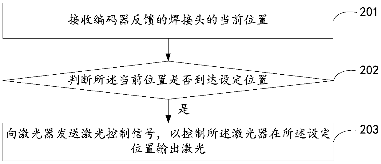
[0082] see figure 2 , is a flow chart of the laser welding control method provided by the embodiment of the present application. The following will be figure 2 The specific process shown will be described in detail.
[0083] Step 201, receiving the current position of the welding head fed back by the encoder.
[0084] Optionally, the target device may be welded according to a preset welding trajectory diagram.
[0085] Since different types of devices need to be soldered in different positions, the soldering density requirements may also be different. Optionally, each type of device may correspond to a welding trace diagram. Optionally, the main controller can run an application program. The application program can plan the movement route of welding for each type of device according to the welding trajectory map of each type of device.
[0086] Optionally, the above-mentioned welding trajectory diagram may be a trajectory diagram directly imported into the above-mentio...
Embodiment 3
[0114] Based on the same application concept, the embodiment of the present application also provides a laser welding control device corresponding to the laser welding control method. Since the problem-solving principle of the device in the embodiment of the present application is similar to the above-mentioned laser welding control method in the embodiment of the present application, therefore For the implementation of the device, reference may be made to the implementation of the method, and repeated descriptions will not be repeated.
[0115] see Figure 5 , is a schematic diagram of the functional modules of the laser welding control device provided in the embodiment of the present application. Each module in the laser welding control device in this embodiment is used to execute each step in the above method embodiment. The laser welding control device includes a receiving module 301, a judging module 302, and a control module 303; wherein,
[0116] The receiving module ...
PUM
 Abstract
Description
Claims
Application Information