Needleless electrostatic spinning device

An electrospinning and recycling device technology, applied in textiles and papermaking, filament/thread forming, fiber processing, etc., can solve problems such as needle blockage, difficulty in controlling the spinning process, and inability to accurately control the shape of the jet flow. Stable, fast and adjustable spinning shape and efficiency

Active Publication Date: 2019-08-16
GUANGDONG UNIV OF TECH
View PDF6 Cites 8 Cited by
  • Summary
  • Abstract
  • Description
  • Claims
  • Application Information

AI Technical Summary

Problems solved by technology

[0003] Most of the existing needle-free electrospinning devices have complex structures, mainly in the form of tips and small holes. Although the problem of needle clogging in traditional needle-based electrospinning devices has been solved and the spinning efficiency has also been increased, there are still problems in spinning. Difficult to control the silk process
[0004] Needleless spinning systems are almost all open systems at present. The concentration of the spinning solution changes with the volatilization of the solvent, which affects the distribution of fiber diameters; at the same time, the spinning process cannot precisely control the jet shape, and it is difficult to follow the preset shape. and size to prepare nanofibers with excellent performance; the spinning process can only be ring-opened due to the volatilization of the solvent, and a large amount of recovery solution is wasted
The collection device of the existing electrospinning device is mainly a collection plate, which can only be translated along the X and Y axes to collect the spinning fibers

Method used


Image

  • Needleless electrostatic spinning device
  • Needleless electrostatic spinning device

Examples


Embodiment Construction

[0022] The following will clearly and completely describe the technical solutions in the embodiments of the present invention with reference to the accompanying drawings in the embodiments of the present invention. Obviously, the described embodiments are only some, not all, embodiments of the present invention. Based on the embodiments of the present invention, all other embodiments obtained by persons of ordinary skill in the art without making creative efforts belong to the protection scope of the present invention.

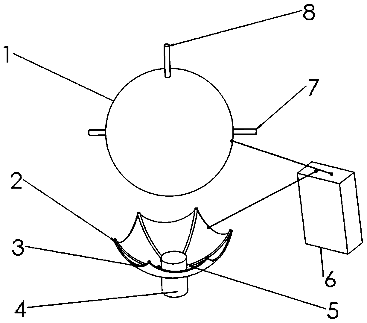
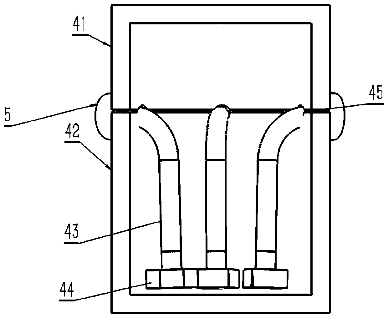
[0023] Please refer to figure 1 and figure 2 , figure 1 A schematic structural view of a centrifugal electrospinning nozzle provided for a specific embodiment of the present invention; figure 2 It is a structural schematic diagram of a liquid supply system of a needle-free electrospinning device provided by a specific embodiment of the present invention.

[0024] A needle-free electrospinning device provided by an embodiment of the present invention inclu...


PUM


Abstract

The invention discloses a needleless electrostatic spinning device. The device comprises a receiving ball, spinneret orifice pipes, an umbrella cover recovery device, a liquid storage tank, a tank cover, liquid supply pipes and liquid supply pumps, wherein the concave surface of the umbrella cover recovery device faces the receiving ball, the receiving ball is located at the upper part of the umbrella cover recovery device, the spinneret orifice pipes are arranged on the inner side of the concave surface of the umbrella cover recovery device, a plurality of spinneret orifices are densely distributed on pipe bodies of the spinneret orifice pipes, the liquid supply pumps are connected with the spinneret orifice pipes through the liquid supply pipes, and the tail ends of the spinneret orificepipes are closed; a backflow gap is formed between the liquid storage tank and the tank cover and used for allowing a solution recovered by the umbrella cover recovery device to flow into the liquidstorage tank. In the specific working process, the surplus solution flows back to the liquid storage tank from the backflow gap through the umbrella cover recovery device and continues to be input into the liquid supply pipes by the liquid supply pumps, so that recycling of the spinning solution is achieved. In the whole process, the spinning solution cannot make contact with air, and accordingly,stable concentration of the spinning solution is maintained, and the diameter of a spinning fiber remains unchanged.

Description

technical field [0001] The invention relates to the technical field of electrostatic spinning, in particular to a needle-free electrostatic spinning device. Background technique [0002] Electrospinning technology is a technology that uses electrostatic field force to produce nanofibers. The principle is that in a high-voltage electrostatic field, a charged polymer solution forms a Taylor cone under the action of an electric field force. When the electric field is large enough, the charged droplet overcomes the surface The tension forms a charged jet, and finally deposits and solidifies into a nanofibrous structure on the collecting mechanism. [0003] Most of the existing needle-free electrospinning devices have complex structures, mainly in the form of tips and small holes. Although the problem of needle clogging in traditional needle-based electrospinning devices has been solved and the spinning efficiency has also been increased, there are still problems in spinning. Th...

Claims


Application Information

Patent Timeline
Patent Type & Authority Applications(China)
IPC IPC(8): D01D5/00
CPCD01D5/0061D01D5/0069D01D5/0076
Inventor 薛增喜王晗陈新杨志军姚敬松辛正一江文佳曾景华
Owner GUANGDONG UNIV OF TECH
Why Eureka
Try Eureka