Non-aqueous electrolyte secondary battery and material for use in same

A non-aqueous electrolyte, secondary battery technology, applied in secondary batteries, battery electrodes, electrode current collector coatings, etc., can solve the problems of unsatisfactory, different degrees of deformation, deterioration of the current collection structure of the positive electrode mixture layer, etc. Effects of improved performance, suppression of thermal runaway, and increased resistance

Active Publication Date: 2019-08-16
MITSUI CHEM INC
View PDF14 Cites 5 Cited by
  • Summary
  • Abstract
  • Description
  • Claims
  • Application Information

AI Technical Summary

Problems solved by technology

[0010] However, if the type of positive electrode active material is changed in the positive electrode mixture layer, the degree of deformation of the positive electrode active material due to the expansion and contraction of the crystal lattice accompanying charge and discharge is different, resulting in the deterioration of the current collection structure in the positive electrode mixture layer. ideal

Method used


Image

  • Non-aqueous electrolyte secondary battery and material for use in same
  • Non-aqueous electrolyte secondary battery and material for use in same
  • Non-aqueous electrolyte secondary battery and material for use in same

Examples


Embodiment 1

[0176] Binder-Solution Preparation

[0177] 10 g of PMMA (molecular weight: 15,000) was added to 115 g of N-methylpyrrolidone (NMP), and stirred for 12 hours to prepare an 8%-PMMA solution. 125 g of the 8%-PMMA solution and 375 g of the 8%-PVDF solution (PVDFW#7200 manufactured by Kureha dissolved in NMP) were mixed and stirred for 12 hours. Thus, an 8%-binder solution (PVDF:PMMA=3:1) was obtained.

[0178] Positive electrode production

[0179] 1. Slurry Preparation

[0180] The slurry was prepared using a 5 L planetary mixer.

[0181] For NCM523 (manufactured by Umicore, the composition formula is LiNi 0.5 co 0.2 mn 0.3 o 2 ) 920g, Super-P (conductive carbon manufactured by TIMCAL Co., Ltd.) 20g, and KS-6 (flaky graphite manufactured by TIMREX Co., Ltd.) 20g were mixed for 10 minutes, and N-methylpyrrolidone (NMP) 100g was added for a further 20 minutes mix.

[0182] Next, 150 g of the 8%-binder solution was added and kneaded for 30 minutes, and then 150 g of th...

Embodiment 2

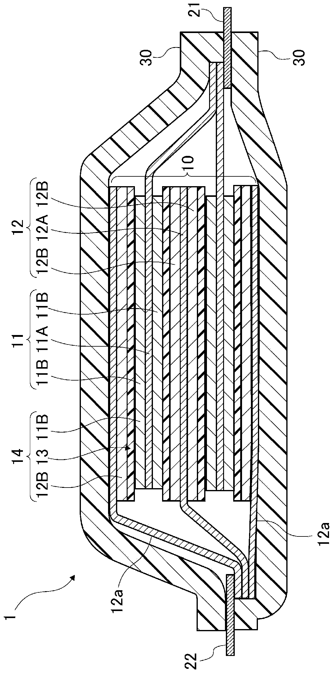
[0212] The positive electrode roll produced in the same manner as in Example 1 was cut into electrodes so as to obtain electrode coating areas (front and back: 174 mm×94 mm) and tab welding blanks to obtain positive electrodes C-2.

[0213] The negative electrode roll produced in the same manner as in Example 1 was divided into electrodes so as to obtain electrode coating areas (front and back: 180 mm×100 mm) and tab welding blanks to obtain negative electrodes A-2.

[0214] battery production

[0215] Laminated battery (design capacity is 5Ah)

[0216] An aluminum tab was bonded to the blank portion of the positive electrode C-2 using an ultrasonic bonding machine. A nickel tab was bonded to the blank portion of the negative electrode A-2 using an ultrasonic bonding machine.

[0217] 1. Cascading

[0218] As the separator, a polyethylene porous membrane (183 mm×100 mm) with a porosity of 45% and a thickness of 25 μm was used (S-2).

[0219] In the order of negative electr...


PUM

PropertyMeasurementUnit
melting pointaaaaaaaaaa

Abstract

The lithium ion secondary battery according to one embodiment of the present invention comprises, in an electrode, an electrode active material, a conductive auxiliary, and a binding material. The binding material is formed from: a binding component that binds the conductive auxiliary and forms conduction paths between the electrode active material; and a melting point depressant that depresses the melting point of the binding component. The melting point depressant is a PTC-functionality-imparting component that reduces the melting start temperature of the binding material and thereby gives the lithium ion secondary battery PTC functionality. When a conductive foreign substance has generated short circuit heat inside the lithium ion secondary battery, the binding material around the foreign substance is melted, and the conduction paths are cut off.

Description

[0001] cross reference [0002] This application is based on Japanese Patent Application No. 2017-1343 and Japanese Patent Application No. 2017-1346 filed in Japan on January 6, 2017, and Japanese Patent Application No. 2017-59725 filed in Japan on March 24, 2017. Right of priority, all the contents described in the above application are directly incorporated into this specification by reference. In addition, the contents described in all the patents, patent applications, and documents cited in this application are directly incorporated in this specification by reference. technical field [0003] The present invention relates to a non-aqueous electrolyte secondary battery and materials used therein, more specifically, to a composite PTC binder material for a non-aqueous electrolyte secondary battery, a positive electrode containing the same, a non-aqueous electrolyte secondary battery, and a lithium-ion secondary battery. secondary battery. Background technique [0004] I...

Claims


Application Information

Patent Timeline
Patent Type & Authority Applications(China)
IPC IPC(8): H01M4/62C08L27/16C08L101/02H01M10/0566
CPCH01M4/62C08L27/16C08L101/02H01M4/366H01M4/622H01M4/623H01M10/0525H01M10/0568H01M10/0569H01M4/505H01M4/525H01M4/1391H01M4/131H01M4/0404H01M4/624H01M2004/028Y02E60/10Y02P70/50
Inventor 山本伸司水野悠远藤裕理
Owner MITSUI CHEM INC
Why Eureka
Try Eureka