Electric automobile power battery frame lifting device and lifting method
A technology of a power battery and a lifting device, which is applied in the automotive field, can solve the problems of the electric vehicle chassis becoming taller, inconvenient to use, and unfavorable for the improvement of the vehicle, and achieves the effect of easy maintenance and replacement, and convenient replacement.
- Summary
- Abstract
- Description
- Claims
- Application Information
AI Technical Summary
Problems solved by technology
Method used
Image
Examples
Embodiment 1
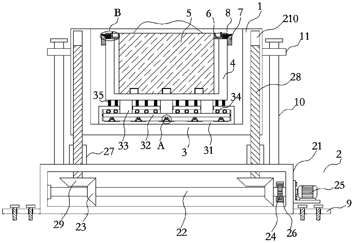
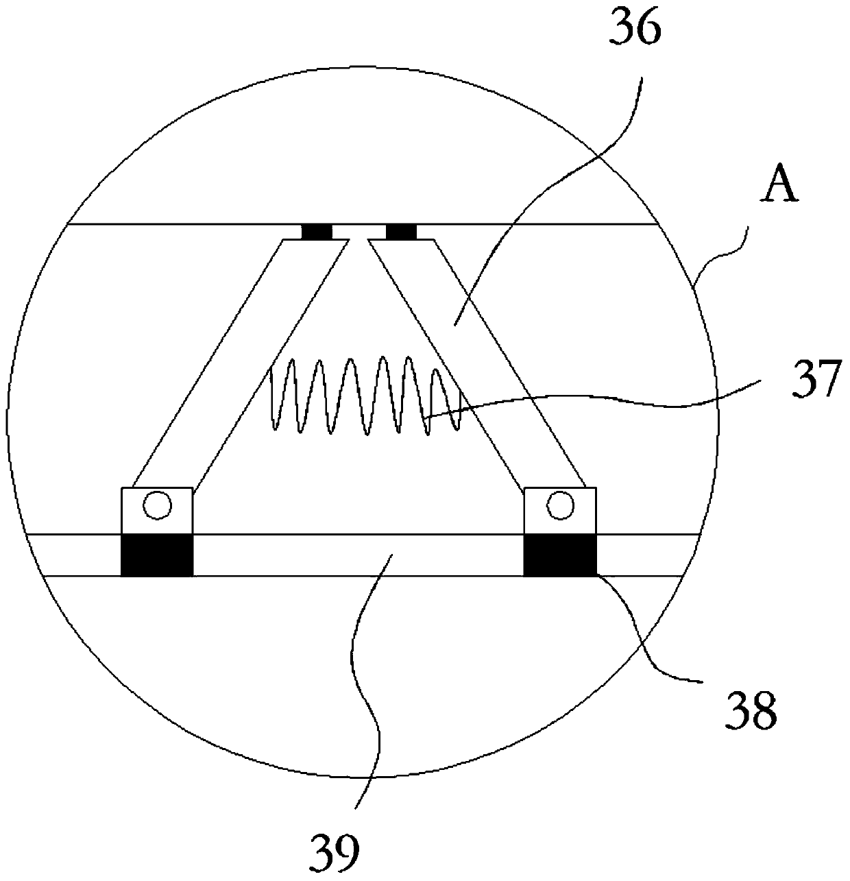
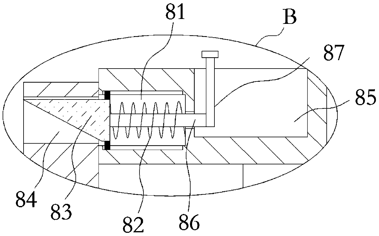
[0034] see Figure 1-4 , an electric vehicle power battery frame lifting device, comprising a lifting frame 1, a lifting mechanism 2 is connected to the lower end of the lifting frame 1, a battery frame 4 is fixedly connected to the bottom inner wall of the lifting frame 1 through a shock absorbing mechanism 3, and the battery frame 4 is installed There is a battery body 5, the upper outer wall of the battery body 5 is symmetrically fixedly connected with two fixed plates 6, the outer wall of the battery frame 4 is fixedly connected with a fixed block 7 corresponding to the fixed plate 6, and the fixed plate 6 and the fixed block 7 pass through a limit Bit mechanism 8 connections;
[0035] Lifting mechanism 2 comprises support box 21, and the inner wall of support box 21 left and right opposite sides is connected with two rotating rods 22 symmetrically rotating back and forth through ball bearings, and the rod wall of rotating rod 22 is fixedly sleeved with two active helical ...
Embodiment 2
[0045] see Figure 5-Figure 6 A lifting device and a lifting method for a power battery frame of an electric vehicle are arranged in a power management system, and a control chip of the power management system controls a driving motor 25 in the lifting device through a circuit connection.
[0046] The power management system also includes: a temperature detection board located at the bottom of the battery frame 4, and a heat dissipation device arranged on the inner side of the battery frame 4; The internal circulating air duct 13 is introduced by the cooling device to exchange the air inside and outside the battery frame 4, and the high-temperature air in the battery body 5 is exported to the battery frame 4 through the cooling fan 12, and the external air introduced first enters the circulating air duct 13 A spiral coil 14 is installed in the circulating air duct 13, and water at a constant temperature is provided inside the spiral coil 14. After the air passes through the sp...
Embodiment 3
[0049] It also includes a heat-conducting tube sleeved in the shock-absorbing rubber ring, and the heat-conducting tube communicates with the spiral coil 14 to form a temperature control path. When the temperature is higher than the predetermined temperature, such as in summer, the rubber ring is cooled by the temperature control device, and at the same time, the heat around the battery is absorbed to prevent the rubber ring from being oxidized and invalidated due to excessive temperature. When the temperature is lower than the predetermined temperature, the rubber ring is kept warm by the temperature control device to prevent the rubber ring from becoming brittle and losing the shock absorption effect when it is cold.
PUM
 Abstract
Description
Claims
Application Information
 - R&D
- Intellectual Property
- Life Sciences
- Materials
- Tech Scout
- Unparalleled Data Quality
- Higher Quality Content
- 60% Fewer Hallucinations
Browse by: Latest US Patents, China's latest patents, Technical Efficacy Thesaurus, Application Domain, Technology Topic, Popular Technical Reports.
© 2025 PatSnap. All rights reserved.Legal|Privacy policy|Modern Slavery Act Transparency Statement|Sitemap|About US| Contact US: help@patsnap.com


