Multi-drive structure of primary air fan for thermal power station
A secondary fan and power plant technology, applied in the direction of machines/engines, liquid fuel engines, mechanical equipment, etc., can solve the problems of high-quality energy waste, etc., to improve the utilization rate, reduce throttling loss, and increase operational flexibility Effect
- Summary
- Abstract
- Description
- Claims
- Application Information
AI Technical Summary
Problems solved by technology
Method used
Image
Examples
specific Embodiment approach 1
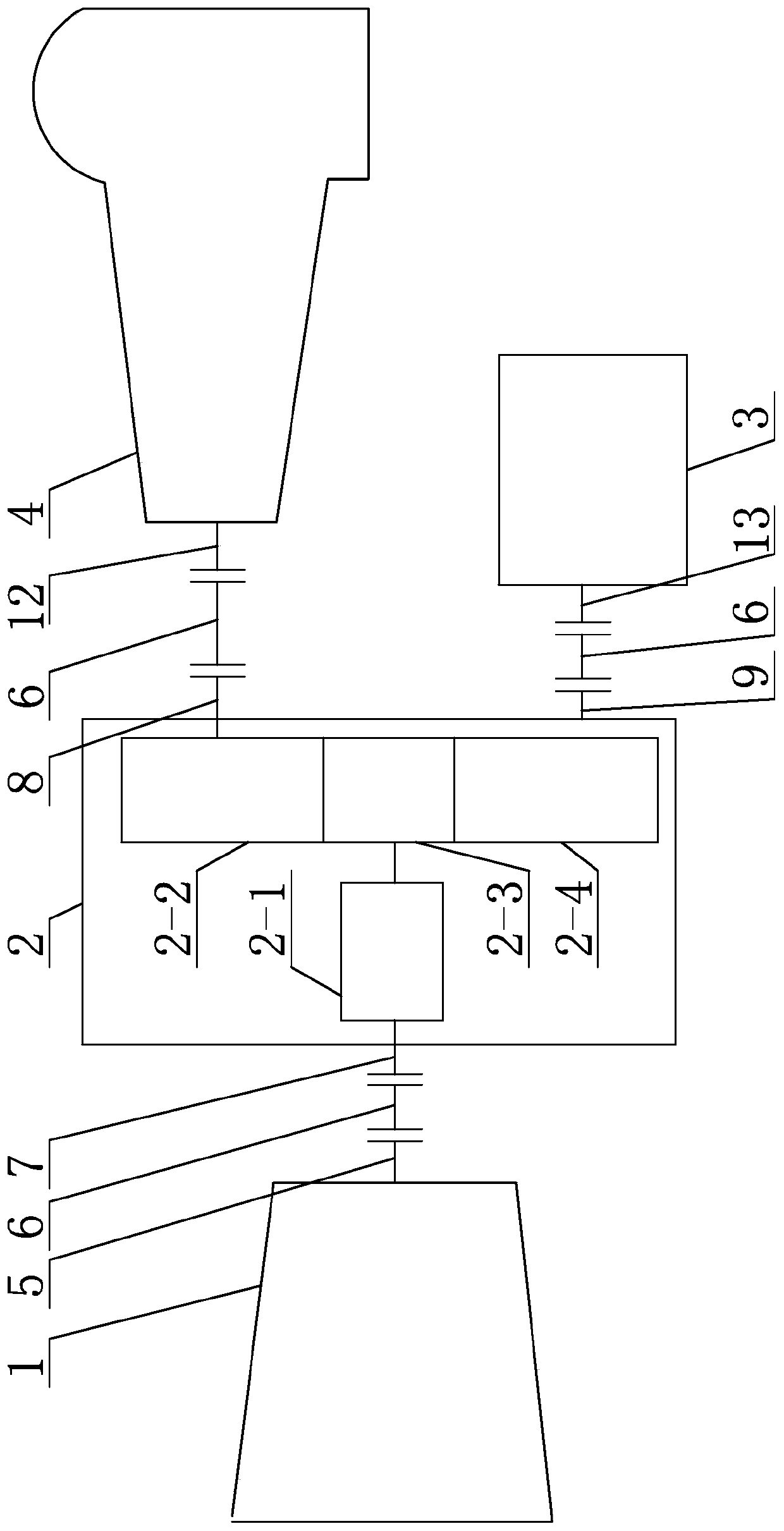
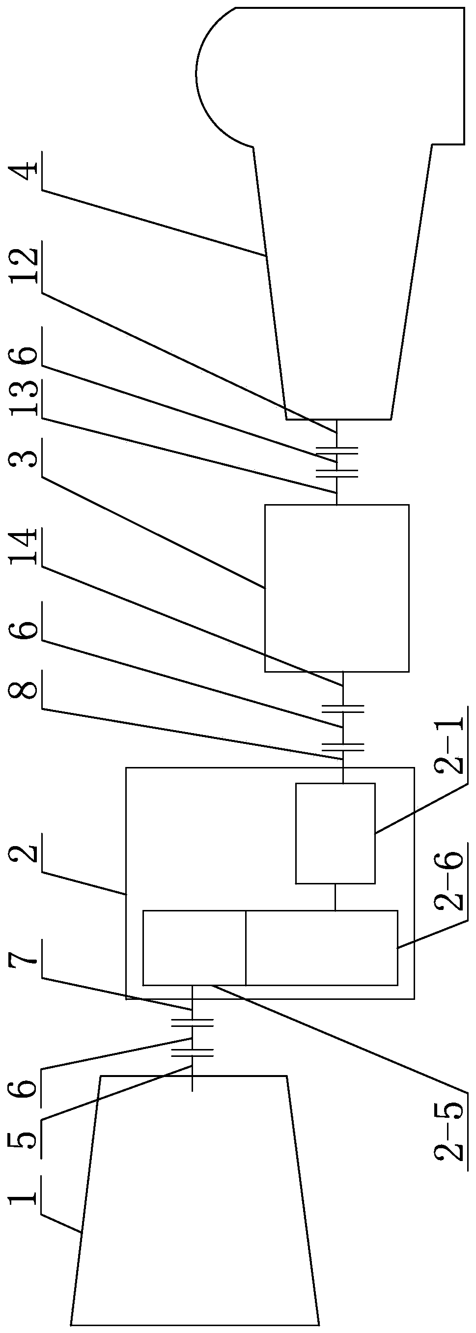
[0018] Specific implementation mode 1: Combination figure 1 This embodiment will be described. In this embodiment, the multi-drive structure of the primary fan of the thermal power plant includes a back pressure machine 1, a multi-shaft variable speed clutch 2, an electric motor 3, a primary fan 4, a back pressure machine output end 5, and a multi-shaft Variable speed clutch input terminal A7, multi-axis variable speed clutch input terminal B9, multi-axis variable speed clutch output terminal 8, primary fan input terminal 12, motor output terminal 13 and three couplings 6, back pressure machine 1 is provided with a back pressure machine Output terminal 5, the multi-axis variable speed clutch 2 is provided with a multi-axis variable speed clutch input terminal A7, a multi-axis variable speed clutch input terminal B9 and a multi-axis variable speed clutch output terminal 8. The primary fan 4 is provided with a primary fan input terminal 12 and a motor 3. A motor output terminal 13...
specific Embodiment approach 2
[0021] Specific implementation manner two: combination figure 1 This embodiment is described. In this embodiment, the multi-shaft transmission clutch 2 includes an automatic synchronization clutch 2-1, a first gear 2-2, a second gear 2-3, and a third gear 2-4. The input terminal of 2-1 is connected with the output terminal 5 of the back pressure machine through the coupling 6, the output terminal of the automatic synchronization clutch 2-1 is connected with the second gear 2-3, and the first gear 2-2 is connected with the input terminal of the primary fan 12 is connected by the coupling 6, the third gear 2-4 and the motor output end 13 are connected by the coupling 6, the first gear 2-2 is meshed with the second gear 2-3, and the second gear 2-3 is The three gears 2-4 mesh.
[0022] The multi-shaft variable speed clutch 2 has one output end and two input ends, and can be connected to two driving devices and one load. In some cases, compared to the coaxial arrangement, it can sav...
specific Embodiment approach 3
[0025] Specific embodiment 3: In this embodiment, the coupling 6 is a diaphragm coupling or a diaphragm coupling.
[0026] The shafting equipment is flexibly connected through a diaphragm coupling or a diaphragm coupling, which can absorb the thermal expansion of the rotor during the operation of the equipment, so that the shafting can run in a hot state to ensure the best working condition.
[0027] Other components and connection modes are the same as in the second embodiment.
PUM
 Abstract
Description
Claims
Application Information
 - R&D
- Intellectual Property
- Life Sciences
- Materials
- Tech Scout
- Unparalleled Data Quality
- Higher Quality Content
- 60% Fewer Hallucinations
Browse by: Latest US Patents, China's latest patents, Technical Efficacy Thesaurus, Application Domain, Technology Topic, Popular Technical Reports.
© 2025 PatSnap. All rights reserved.Legal|Privacy policy|Modern Slavery Act Transparency Statement|Sitemap|About US| Contact US: help@patsnap.com


