High-gain log periodic antenna based on non-resonant superinterface

A logarithmic periodic antenna and non-resonant technology, which is applied to resonant antennas, antenna arrays powered separately, antennas, etc., can solve the problems of large loss, limited application in the communication field, strong dispersion, etc., to increase gain, realize miniaturization, The effect of reducing the gain difference

Pending Publication Date: 2019-08-20
EAST CHINA NORMAL UNIV
View PDF0 Cites 2 Cited by
  • Summary
  • Abstract
  • Description
  • Claims
  • Application Information

AI Technical Summary

Problems solved by technology

The problem is that the zero-refractive index structure is based on the resonance characteristics of the material, which has a large loss and strong dispersion, which limits its application in the field of communication.

Method used


Image

  • High-gain log periodic antenna based on non-resonant superinterface
  • High-gain log periodic antenna based on non-resonant superinterface
  • High-gain log periodic antenna based on non-resonant superinterface

Examples


Embodiment 1

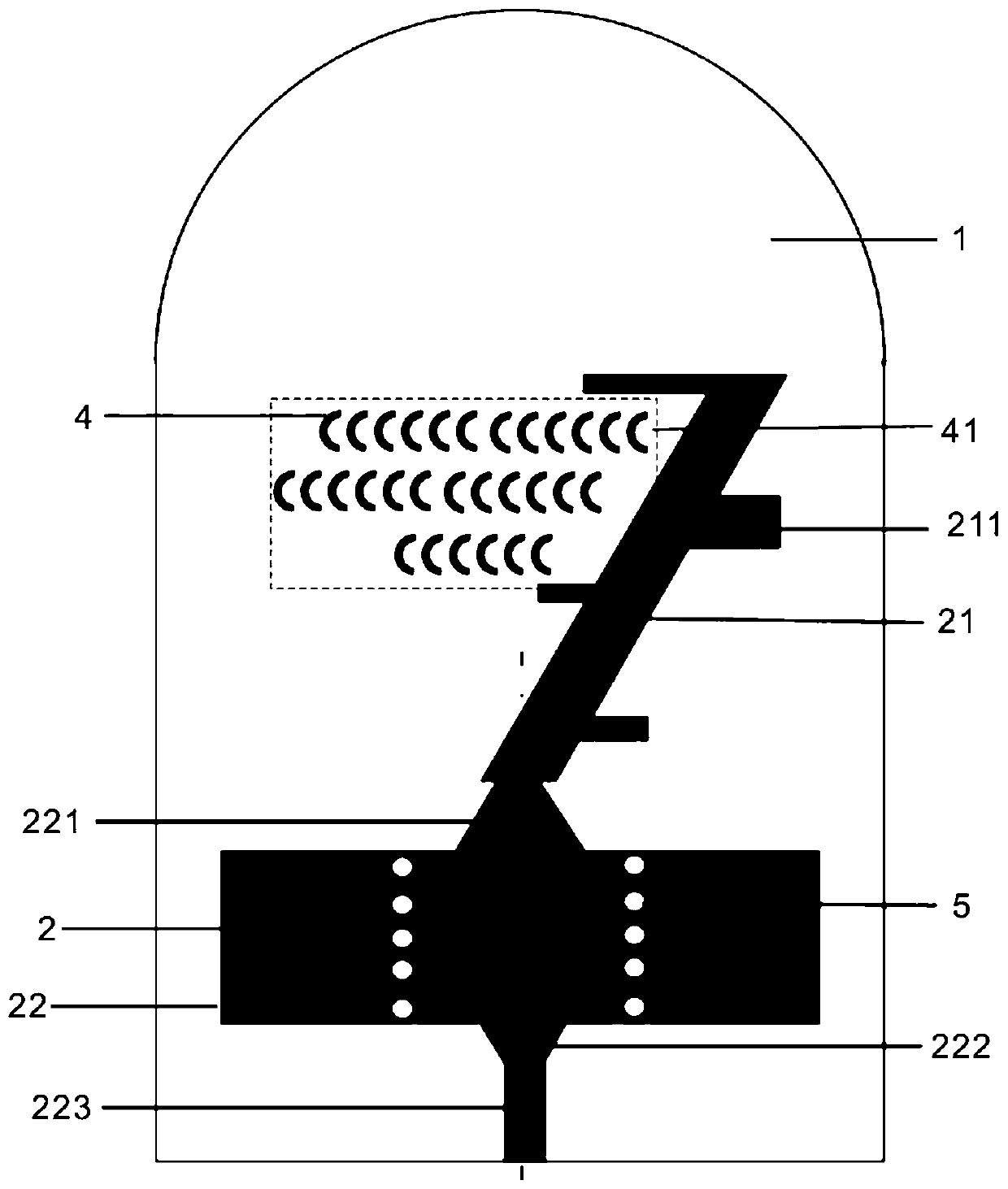
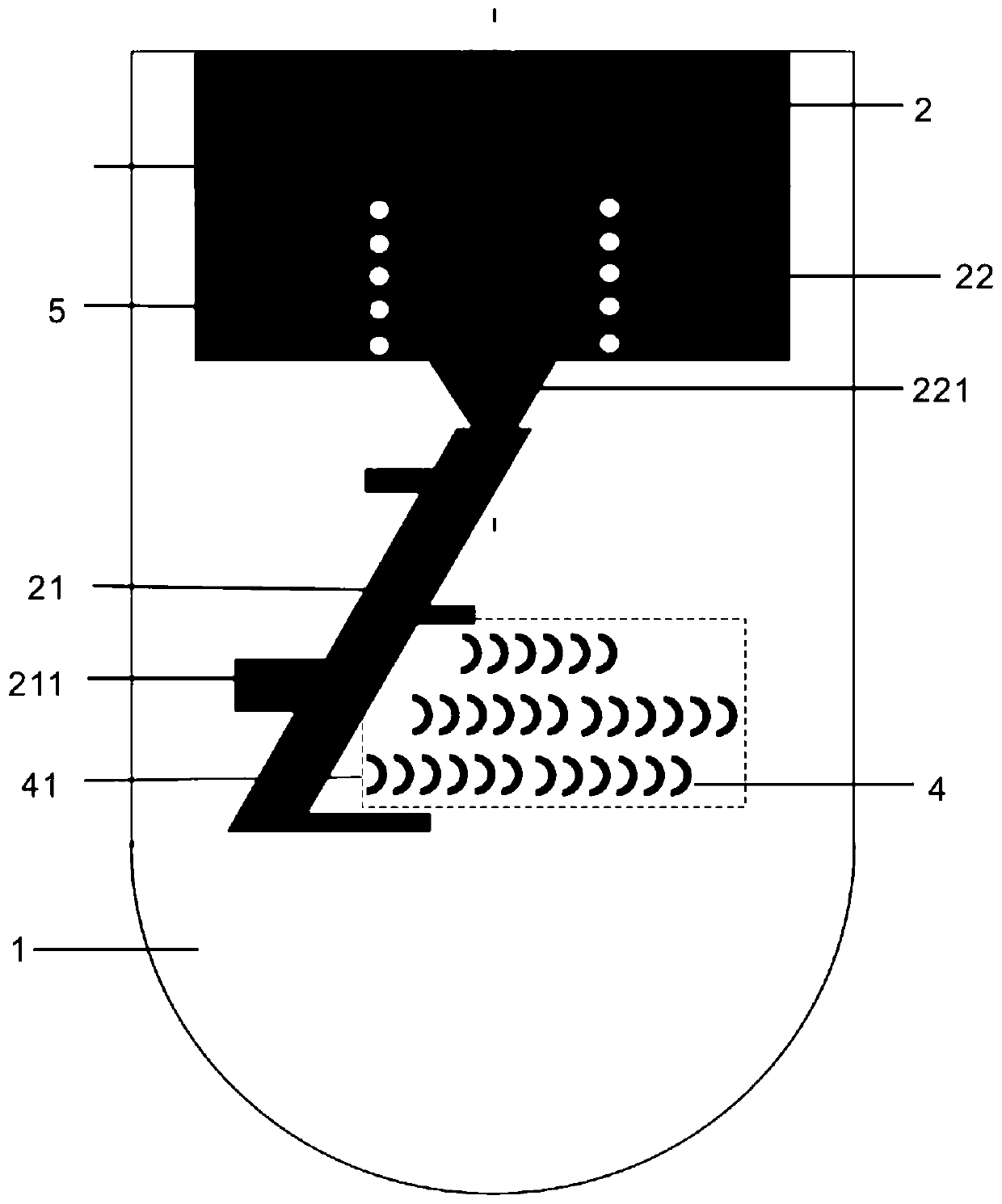
[0046] refer to Figure 7 , Figure 12 , the non-resonant super-interface 41 is arranged in 3 rows, and loaded in the middle of the dipole array 211. The simulation and test results show that the antenna gain is significantly improved in the low frequency range of 27-29 GHz when the structure of the non-resonant super-interface 41 is loaded. The gain value at low frequency is improved, and the gain difference between it and the high frequency point is reduced, which is beneficial to its application in wireless communication systems. The gain results are shown in Figure 12 in case 2; see the results of the original antenna Figure 12 in case 1.

Embodiment 2

[0048] refer to Figure 8 , Figure 12 , the non-resonant super-interface 41 is arranged in 6 rows and 3 columns plus 6 rows and columns, and loaded on the upper part of the dipole array 211. The simulation and test results show that the antenna gain value increases over the entire frequency band when the structure of the non-resonant super-interface 41 is loaded. 1-1.85dB, the gain result see Figure 12 in case 3.

Embodiment 3

[0050] refer to Figure 9 , Figure 11 , Figure 12 , the non-resonant superinterface 41 is arranged in 6 rows and 3 columns plus 6 rows and columns, loaded on the top of the dipole array 211, the non-resonant superinterface 41 is arranged in 3 rows, and loaded in the middle of the dipole array 211, simulation and test results It shows that loading the structure of the non-resonant superinterface 41 not only reduces the gain difference between the low frequency band and the high frequency band, but also improves the gain values ​​at all frequency points. The gain results are shown in Figure 11 , Figure 12 , the gain increment can reach up to 4dB, and the gain float is also reduced from 5.3dB to 3.4dB.

[0051] refer to Figure 11 , the feed port S of Embodiments 1, 2 and 3 of the present invention 11 Satisfied that the entire working bandwidth is below -10dB.

[0052] refer to Figure 10 , the non-resonant superinterface 41 of the present invention is within the 27GHz...


PUM


Abstract

The invention discloses a high-gain log periodic antenna based on a non-resonant superinterface, which comprises a Rogers RT5880 dielectric substrate, an upper metal layer, a lower metal layer and metal semi-rings. According to the invention, two metal patches are etched on the positive and negative sides of the Rogers RT5880 dielectric substrate, two layers of dipole arrays are arranged in a mirror symmetry manner, and the dipole arrays are connected by an inclined feeder. The feeing mode is substrate integrated waveguide feeding. The non-resonant superinterface is composed of metal semi-circular patches, and can be equivalent into a gradient lens with the refractive index being 1.5 constantly within an operating frequency band of 27-40GHz. When the non-resonant superinterface is set between symmetrically arranged dipoles, the low-frequency band gain of the antenna is significantly improved, and the difference between the low-frequency band gain and the high-frequency band gain is reduced; and when the non-resonant superinterface is loaded above the dipoles, the antenna gain is improved in the whole operating frequency band. The gain of the superinterface log periodic antenna is improved by 1-4dB by combining the above two arrangement modes, the distribution of gain values in the low frequency band and the high frequency band is more uniform, the floating amount of the gain isreduced from 5.3dB to 3.4dB, and the antenna is enabled to have high application values in a wireless communication system.

Description

technical field [0001] The invention relates to the technical field of communication equipment, in particular to a high-gain logarithmic periodic antenna based on a non-resonant superinterface. Background technique [0002] Broadband directional antenna is an important device in the wireless communication front-end system, which is constantly developed and improved with the needs of the times. Broadband antennas are also called non-frequency-variable antennas, that is, this type of antenna keeps its important characteristics, including pattern, polarization, and impedance, within a specific wide frequency range. The log-periodic dipole array antenna is one of the widely used frequency-invariant antennas, and has received extensive attention since it was proposed in the 1960s. Due to the low directivity and large size of the traditional log-periodic antenna, how to improve the antenna gain and reduce the size has become the research focus of the log-periodic antenna. The mo...

Claims


Application Information

Patent Timeline
IPC IPC(8): H01Q1/38H01Q1/50H01Q9/16H01Q19/06H01Q21/00H01Q21/06
CPCH01Q1/38H01Q1/50H01Q21/062H01Q19/06H01Q9/16H01Q21/0006
Inventor 黄家维翟国华王茜谢仁盛丁军
Owner EAST CHINA NORMAL UNIV
Why Eureka
Try Eureka