A kind of tracheal cannula for antibacterial filtration
A technology of tracheal cannula and cannula, which is applied in the direction of tracheal intubation, medical equipment, and other medical equipment, and can solve the problems of lack of air filtration and humidification of patients with tracheitis
- Summary
- Abstract
- Description
- Claims
- Application Information
AI Technical Summary
Problems solved by technology
Method used
Image
Examples
Embodiment 1
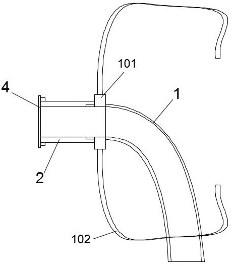
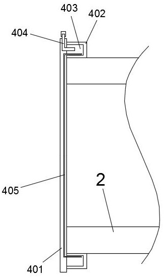
[0033] Such as figure 1 and 2As shown, a tracheal sleeve for antibacterial filtration includes an arc-shaped sleeve body 1 and a fixing bracket 101 arranged on the upper end of the sleeve body 1, and the fixing bracket 101 is fixed to it by the fixing bands 102 provided on its two sides. It is fixed on the neck of the patient, and a cannula extension tube 2 connected to the cannula body 1 is arranged on the fixed bracket 101, and a bacteriostatic filter mechanism 4 is arranged at the end of the cannula extension tube 2. The filter mechanism 4 includes an end cap 401 that blocks the end of the sleeve extension pipe 2 and an annular connection portion 402 that is arranged on one side of the end cap 401 and is connected with the sleeve extension pipe 2. The middle part of the end cap 401 is a circular opening hole, and the circular through hole communicates with the sleeve extension tube 2, and the end of the sleeve extension tube 2 is closed with gauze 405, and the edge of the ...
Embodiment 2
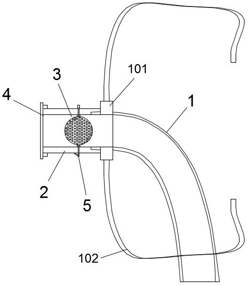
[0037] Since the gauze plays a filtering role in use, after a period of use, bacteria will grow on its surface. In order to kill bacteria and prevent bacteria from entering the trachea, this embodiment is improved on the basis of embodiment 1. Its main structure is the same as Embodiment 1 is the same, the difference is: as Figure 3-7 As shown, the sleeve extension tube 2 is provided with a gauze disinfection mechanism 3, and the gauze disinfection mechanism 3 includes a fixing ring 302 arranged around the inner wall of the sleeve extension tube 2 and a flip for cutting or opening the sleeve extension tube 2. Plate 301, the flap 301 is rotated and installed in the inner ring of the fixed ring 302 through the rotating rod 304 and the rotating pin shaft 303 on both sides respectively, and the gap between the outer side of the flap 301 and the inner wall of the fixed ring 302 is covered by a silicone seal ring 307 sealing; the rotating pin shaft 303 and the rotating rod 304 are ...
Embodiment 3
[0045] This embodiment is an improvement made on the basis of embodiment 2, and its main structure is the same as that of embodiment 2, the difference is that: Figure 4 and 7 As shown, one end of the liquid inlet elastic hose 305 is fixed in the buffer chamber 3011, and the other end is passed through the rotating pin shaft 303, and protrudes from the end of the rotating pin shaft 303, so that it can be fed to the buffer chamber by the liquid pressurization device. Inject disinfectant into it.
[0046] The liquid pressurizing device in this embodiment is an air bag, or other existing equipment, such as filling the air bag with disinfectant, and quickly squeezing the air bag, so that the disinfectant in the air bag can be ejected quickly, and then sprayed on the gauze. The volume of cavity 3011 is relatively small, and only one airbag with a volume of at least 1 decimeter is needed to quickly inject the disinfectant onto the gauze 405, and the 1 decimeter airbag can also be s...
PUM
 Abstract
Description
Claims
Application Information
 - R&D
- Intellectual Property
- Life Sciences
- Materials
- Tech Scout
- Unparalleled Data Quality
- Higher Quality Content
- 60% Fewer Hallucinations
Browse by: Latest US Patents, China's latest patents, Technical Efficacy Thesaurus, Application Domain, Technology Topic, Popular Technical Reports.
© 2025 PatSnap. All rights reserved.Legal|Privacy policy|Modern Slavery Act Transparency Statement|Sitemap|About US| Contact US: help@patsnap.com


