RRT unmanned aerial vehicle path planning method based on driver visual perception imitation

A technology of path planning and visual perception, which is applied in the control of finding targets, etc., can solve problems such as slow search speed and search failure, and achieve the effect of enhancing purpose, improving speed and good orientation.

Pending Publication Date: 2019-08-23
HARBIN INST OF TECH
View PDF4 Cites 9 Cited by
  • Summary
  • Abstract
  • Description
  • Claims
  • Application Information

AI Technical Summary

Problems solved by technology

[0007] In order to solve the problem that the existing unmanned aerial vehicles have slow search speed and sometimes search failure when planning paths in complex blocked environments, the present invention provides an RRT unmanned aerial vehicle path planning method that imitates the driver's visual perception

Method used


Image

  • RRT unmanned aerial vehicle path planning method based on driver visual perception imitation
  • RRT unmanned aerial vehicle path planning method based on driver visual perception imitation
  • RRT unmanned aerial vehicle path planning method based on driver visual perception imitation

Examples


specific Embodiment approach 1

[0043] Specific embodiment one: the RRT unmanned aerial vehicle path planning method of imitation driver's visual perception that this embodiment provides, specifically comprises the following steps:

[0044] Setting several driver visual guidance points in the state space as the nodes that must pass through the path of the UAV can be regarded as the intermediate target points obtained by dividing the flight path into segments under the imitation of the driver's subjective consciousness. The driver visual guidance points The path between the starting point and the target point of the UAV is divided into multiple track segments; the improved RRT algorithm is used for path planning for each track segment, and the driver's visual perception is added to the RRT planning algorithm, which can make The algorithm has better orientation when searching, and the improved RRT algorithm introduces the idea of ​​target bias in the traditional RRT algorithm (setting the probability threshold ...

specific Embodiment approach 2

[0053] Specific implementation mode two: combination image 3 , Figure 4 The present embodiment is described. The difference between this embodiment and the specific embodiment one is that the improved RRT algorithm considers the constraints brought by the physical performance of the UAV itself and specifically includes:

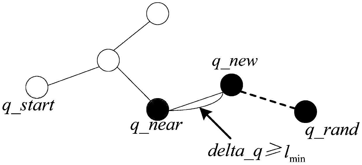
[0054] Constrain the length of the UAV's minimum track segment l min Combined with the extended step delta_q in the RRT algorithm, it is guaranteed that the distance from the nearest neighbor point q_near to the extended step delta_q of the newborn node q_new is not less than l min ;Such as image 3 shown;

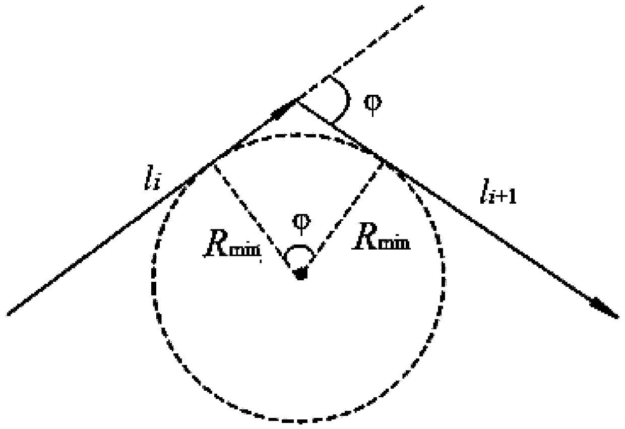
[0055] Transform the drone's minimum turning radius constraint into a maximum turning angle constraint, such as Figure 4 As shown, the turning angle between two consecutive paths is limited, so that the UAV turning angle The cosine value of is not less than the maximum turning angle The cosine value of , as shown in formula (4):

[0056]

...

specific Embodiment approach 3

[0059] Specific implementation mode three: the difference between this embodiment mode and specific implementation mode two is that the improved RRT algorithm adds the track distance constraint specifically as follows:

[0060] The maximum range constraint of UAV is improved, and the track distance constraint of UAV is introduced. The length of the UAV's track distance constraint is limited to k times the straight-line distance between the starting position and the target position; assuming that the straight-line distance from the starting position to the target position is d, the length of the track distance constraint is set to d max = k d; k ≥ 1; in this way, the track distance planned by the algorithm can be shortened, and a relatively better (shorter) path planning can be obtained.

[0061] Other steps and parameters are the same as in the second embodiment.


PUM


Abstract

The invention provides an RRT unmanned aerial vehicle path planning method based on driver visual perception imitation, and belongs to the technical field of unmanned aerial vehicle control. A plurality of driver visual guide points are arranged in a state space to serve as nodes which must be passed in an unmanned aerial vehicle path, and the driver visual guide points divide the unmanned aerialvehicle path between a starting point and a target point into a plurality of track segments; the path planning is carried out on each track segment by applying an improved RRT algorithm; the improvedRRT algorithm introduces a target deflection thought in a traditional RRT algorithm; a constraint caused by the physical performance of an unmanned aerial vehicle is considered, and a track distance constraint is added; and the path planning of the unmanned aerial vehicle is obtained in combination with planning results of all the track segments. According to the method, the problems that an existing unmanned aerial vehicle is low in search speed and sometimes has search failure during the path planning in a complex blocked environment are solved. The method can be used for the path planning of the unmanned aerial vehicle in the complex environment.

Description

technical field [0001] The invention relates to a path planning method for an unmanned aerial vehicle, and belongs to the technical field of unmanned aerial vehicle control. Background technique [0002] UAV mission planning and control system is an important part of UAV system, and path planning is one of the key technologies. To put it simply, UAV path planning is to fully consider the various constraints and mission requirements of UAV in the environment state space, and plan a feasible path for UAV from the initial position to the target point. The driver's visual behavior is the perceived behavior of the driver to obtain information through vision during driving. It is mostly used in the field of automobiles or unmanned vehicles. At present, there is no research on the combination of driver's visual behavior and UAV path planning. [0003] Kandil Farid I and Rotter Alexander found that when the driver is in such figure 1 In the driving scene shown, 75% of the driver’s...

Claims


Application Information

Patent Timeline
Patent Type & Authority Applications(China)
IPC IPC(8): G05D1/12
CPCG05D1/12
Inventor 谭立国宋申民张耀华
Owner HARBIN INST OF TECH
Why Eureka
Try Eureka