
Thermal management system and method for electric vehicle batteries based on memory alloy

An electric vehicle, memory alloy technology, applied in electric vehicles, batteries, secondary batteries, etc., can solve the problems of heat dissipation, complex control system, difficult battery system temperature adjustment, etc., and achieve automatic control of heat dissipation intensity and simplified control. System structure, the effect of enhancing temperature uniformity

Active Publication Date: 2019-08-23
SHANDONG UNIV
View PDF7 Cites 18 Cited by
  • Summary
  • Abstract
  • Description
  • Claims
  • Application Information

AI Technical Summary

Problems solved by technology

[0004] As far as the inventor knows, the power battery thermal management systems currently used in electric vehicles are mainly air-cooled and liquid-cooled, but most of them only focus on controlling the temperature range or improving temperature consistency. Complexity, low reliability, high energy consumption and cost
For example, Chinese patent CN208460930U provides a liquid-cooled power battery thermal management system. The battery can be cooled by liquid cooling plates arranged at the bottom and sides of the battery, so that the battery can reach the rated operating temperature in a short time. The flow rate of the cold plate is the same, so it is impossible to carry out targeted heat dissipation according to the actual heat generation of each battery module. When a certain battery module generates a large amount of heat, it will destroy the temperature consistency between the battery modules; The system has only two working modes, and it is difficult to adjust the temperature of the battery system according to different working conditions; in addition, there are many sensors in the system, and the production cost is high

Method used


Image

  • Thermal management system and method for electric vehicle batteries based on memory alloy
  • Thermal management system and method for electric vehicle batteries based on memory alloy
  • Thermal management system and method for electric vehicle batteries based on memory alloy

Examples


Embodiment Construction

[0062] The present disclosure will be further described below in conjunction with the accompanying drawings and embodiments.

[0063] It should be noted that the following detailed description is exemplary and intended to provide further explanation of the present disclosure. Unless defined otherwise, all technical and scientific terms used herein have the same meaning as commonly understood by one of ordinary skill in the art to which this disclosure belongs.

[0064] It should be noted that the terminology used herein is only for describing specific embodiments, and is not intended to limit the exemplary embodiments according to the present disclosure. As used herein, unless the context clearly dictates otherwise, the singular is intended to include the plural, and it should also be understood that when the terms "comprising" and / or "comprising" are used in this specification, they mean There are features, steps, operations, means, components and / or combinations thereof.

...


PUM


Abstract

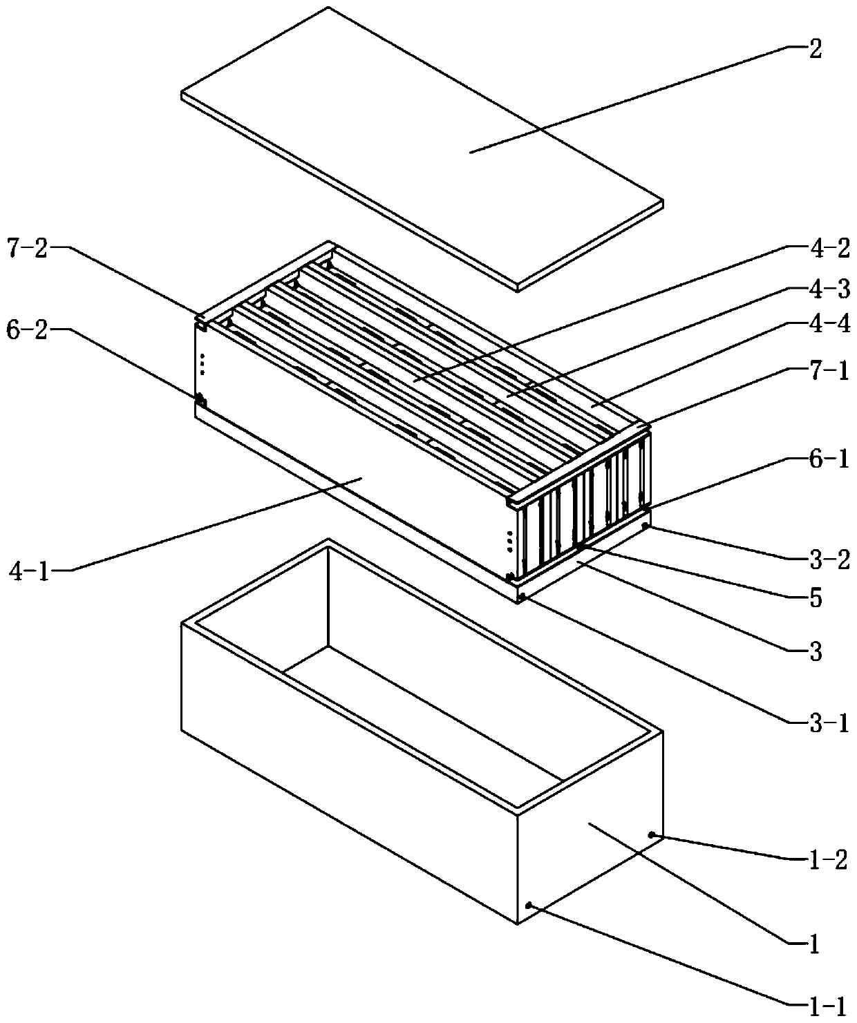
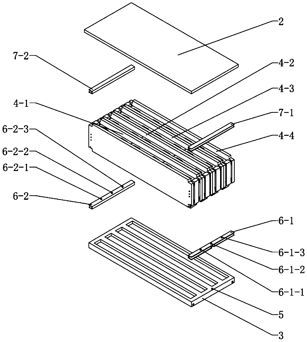
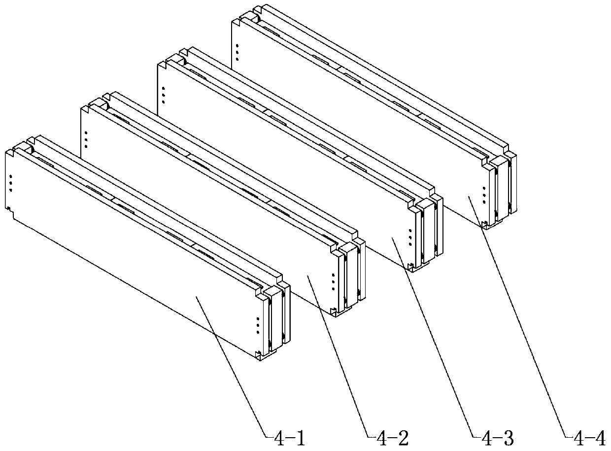
The invention provides a thermal management system and method for electric vehicle batteries based on a memory alloy. The thermal management system comprises a battery box, wherein the battery box accommodates a plurality of variable heat transfer coefficient heat collection modules with the same structure, the variable heat transfer coefficient heat collection modules are sequentially arranged side by side to form a variable heat transfer coefficient heat collection unit, and the edge is connected with the inner wall of the battery box through a sliding rail; each variable heat transfer coefficient heat collection module includes two heat collection plates which are arranged side by side and have a certain spacing, the two heat collection plates are provided with a plurality of single batteries arranged side by side therebetween, the end parts of the two heat collection plates are connected through a memory alloy plate, the memory alloy plate is tightly contacted with the corresponding single batteries, the two heat collection plate are further provided with an elastic member therebetween, and the spacing between the two heat collection plate can vary with the size of the memory alloy plate. The thermal management system can automatically adjust the heat dissipation intensity according to the temperature of the battery system, and improve the temperature consistency inside thebattery system at the same time. In addition, the thermal management system is simple in structure and low in energy consumption.

Description

technical field [0001] The disclosure belongs to the technical field of battery management, and in particular relates to a memory alloy-based electric vehicle battery thermal management system and method. Background technique [0002] The statements in this section merely provide background information related to the present disclosure and do not necessarily constitute prior art. [0003] As the power source of electric vehicles, the power battery system is closely related to the performance of the vehicle. In electric vehicles, each battery cell is usually connected in series and parallel to form a battery module, and multiple battery modules are then connected in series and parallel to form a battery system to provide suitable voltage and sufficient power. Since the performance of a battery cell is related to its internal electrochemical reaction process, the battery system can only obtain the best working condition in a certain temperature range; The battery cell itself...

Claims


Application Information

Patent Timeline
IPC IPC(8): H01M10/613H01M10/617H01M10/625H01M10/637H01M10/653H01M10/6555H01M10/6556H01M10/6567B60L58/26H01M2/10
CPCB60L58/26H01M2220/20H01M10/613H01M10/617H01M10/625H01M10/637H01M10/653H01M10/6555H01M10/6556H01M10/6567H01M50/20Y02E60/10Y02T10/70
Inventor 王亚楠王晨浩王正坤李华厉青峰练晨
Owner SHANDONG UNIV
Learn More