Broadband low-profile dielectric patch antenna with anisotropic characteristics

An anisotropic, patch antenna technology, applied in the direction of antenna, antenna grounding device, antenna grounding switch structure connection, etc., can solve problems such as large-scale application obstacles, theoretical analysis of dielectric patch antennas, etc.

Active Publication Date: 2019-08-23
ZHONGTIAN BROADBAND TECH +1
View PDF1 Cites 31 Cited by
  • Summary
  • Abstract
  • Description
  • Claims
  • Application Information

AI Technical Summary

Problems solved by technology

However, so far, there has been no theoretical analysis for dielectric patch antennas
In addition, the bandwidth of dielectric patch antennas operating in the microwave band is only about 1%, which will be a hindrance for large-scale applications

Method used


Image

  • Broadband low-profile dielectric patch antenna with anisotropic characteristics
  • Broadband low-profile dielectric patch antenna with anisotropic characteristics
  • Broadband low-profile dielectric patch antenna with anisotropic characteristics

Examples


Embodiment Construction

[0019] The present invention will be further described below in conjunction with the accompanying drawings and specific embodiments.

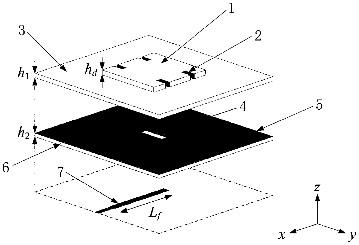
[0020] In this example, first use figure 1 The unslotted dielectric patch 1 and the upper dielectric substrate 3 constitute the resonator of the antenna, and a theoretical analysis is carried out on it. The four sides of the dielectric patch resonator along the z-axis are regarded as magnetic walls, and the metal reflective floor at the bottom is regarded as electric walls. Due to the electric wall, it is possible to mirror the dielectric patch resonator and the main mode (lowest order resonant mode) TM 101 electric field distribution. When the thickness of a single material is much smaller than the wavelength of a free space, the stacked dielectric patch resonator can be approximated as an anisotropic medium with an equivalent dielectric constant ε rx =23.4,ε ry =23.4,ε rz =6.35. A dielectric patch resonator with anisotropic properties c...


PUM


Abstract

The invention discloses a broadband low-profile dielectric patch antenna with anisotropic characteristics. The antenna comprises a lower dielectric substrate, a metal reflection floor, an upper dielectric substrate and a dielectric patch which are sequentially laminated from bottom to top. The lower surface of the lower dielectric substrate is provided with a microstrip feeder line used for coupling feed. A gap is formed on the vertical split surface of the metal reflection floor, and the projection of the microstrip feeder line on the metal reflection floor is perpendicularly intersected withthe gap; the dielectric patch is provided with two pairs of grooves with inner walls printed with metal and symmetrically arranged relative to the center line of the dielectric patch, and the openingdirection of the grooves is perpendicular to the microstrip feeder line. The anisotropic characteristics of a dielectric patch resonator are firstly utilized to improve the gain of the antenna. Moreover, the larger the dielectric constant difference between the dielectric patch and the upper dielectric substrate is, the higher the gain of the antenna is. And then, the multi-mode property of the dielectric patch is fully utilized, and the high-order mode TM121 mode is close to the TM101 mode by introducing a silver coating groove, so that the bandwidth of the antenna is expanded.

Description

technical field [0001] The invention relates to the technical field of wireless communication, in particular to a wide-band low-profile dielectric patch antenna with anisotropic characteristics. Background technique [0002] Metal patch antennas and dielectric resonator antennas are two well-known antennas that are widely used in modern wireless communications. Metal patch antennas have many advantages over dielectric resonator antennas, such as low profile and high gain, and many technologies have been developed to expand the operating bandwidth to overcome its important disadvantage of narrow bandwidth, because broadband antennas can cover more communications frequency band, instead of multiple narrowband antennas. This can not only improve the efficiency of the wireless communication system, but also reduce the number of antennas, processing costs and serious coupling effects between antennas. However, due to the gradual crowding of low frequencies, the frequency of the...

Claims


Application Information

Patent Timeline
Patent Type & Authority Applications(China)
IPC IPC(8): H01Q1/38H01Q1/48H01Q1/50H01Q19/10
CPCH01Q1/38H01Q1/48H01Q1/50H01Q19/104
Inventor 陈建新王雪颖唐世昌杨汶汶
Owner ZHONGTIAN BROADBAND TECH
Why Eureka
Try Eureka