Laser cutting device

A technology of laser cutting and equipment, applied in laser welding equipment, welding equipment, metal processing equipment and other directions, can solve the problems of complex structure of sorting robot equipment, complex structure of laser cutting machine tools, inability to identify different finished parts well, etc. The effect of reducing deviation, precise cutting, automatic blanking, and precise cutting

Pending Publication Date: 2019-08-27
河南力锋科技有限公司 +1
View PDF12 Cites 13 Cited by
  • Summary
  • Abstract
  • Description
  • Claims
  • Application Information

AI Technical Summary

Problems solved by technology

However, the structure of the sorting robot equipment is complicated, and manual confirmation is required for each finished workpiece to be grabbed during use, and the set suction cup is a consumable item that needs to be replaced frequently; and in the public automatic loading and unloading sorting and palletizing system, th

Method used


Image

  • Laser cutting device
  • Laser cutting device
  • Laser cutting device

Examples


Embodiment approach 1

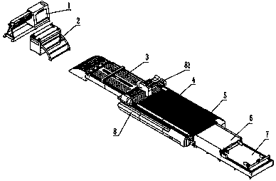
[0091] The overall structure of the laser cutting equipment of the present invention is as follows: figure 1 As shown, the laser cutting equipment is provided with a main bed 8 and is provided with the following working units from back to front, that is, a feeder 3, a clean material cutting area 4, a rotary table 5, a conveyor 6 and a stacker 7. The material cutting area 4 and the rotating worktable 5 are fixed together on the main bed 8, and the rest of the working units are fixed on the ground by anchor bolts; the main bed 8 is also provided with a laser cutting head assembly 81. Set above the clean material cutting area 4 and the rotary table 5. During specific implementation, a leveler 2 and a material rack 1 are also provided at the rear of the feeder 3, and the leveler 2 is provided with a leveler roller, which can roll the coiled sheet material flat, which is beneficial to feeding and laser cutting; The specific structures and usage methods of the material rack and the...

Embodiment approach 2

[0137] Figure 16 It shows the overall structure of another laser cutting equipment of the present invention. The laser cutting equipment is provided with a main bed 8 and is provided with the following working units from back to front, namely material rack 1, leveling machine 2, feeder 3, clean material cutting Area 4, rotating table 5, conveyor 6 and stacker 7, the clean material cutting area 4 and rotating table 5 are fixed on the main bed 8 together, and the rest of the working units are fixed on the ground by anchor bolts ; The main bed 8 is also provided with a laser cutting head assembly 81, and the laser cutting head assembly 81 is arranged above the clean material cutting area 4 and the rotating table 5;

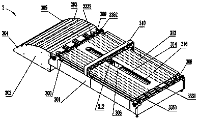
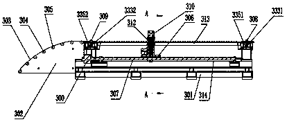
[0138] Feeder for laser cutting equipment 3 such as Figure 17-18 As shown, the feeding machine 3 is provided with a feeding machine body 301 and a feeding idler 302, and the feeding idler 301 is arranged at the rear end of the feeding machine body 301; the feeding...


PUM


Abstract

The invention belongs to the technical field of metal plate production equipment, and particularly relates to a laser cutting device. The laser cutting device is provided with a main lathe bed (8), afeeding machine (3), a clean material cutting area (4) and a rotary workbench (5), wherein the feeding machine (3), the clean material cutting area (4) and the rotary workbench (5) are arranged from back to front; the feeding machine (3) is provided with a feeding rail (314), a feeding crossbeam (310) and a floating clamp (312); the clean material cutting area (4) is provided with a clean materialcutting support bar (41), a clean material cutting servo motor (42) and a stop device; and the rotary workbench (5) is provided with a rotary support bar (51), a rotary servo motor (52), a chain support rail (53) and a supporting bracket (54). According to the laser cutting machine, the feeding machine can achieve high-precision positioning and automatic deviation rectifying through plate limiting and can achieve automatic feeding; a plate is accurately positioned by the clean material cutting area so to be cleaned and cut and is then conveyed to the rotary workbench to be cut into a workpiece; and laser cutting based on automatic feeding and discharging is achieved, and the production efficiency is improved.

Description

technical field [0001] The invention belongs to the technical field of sheet metal production equipment, and in particular relates to a laser cutting equipment. Background technique [0002] Laser cutting machine is the equipment used for cutting and blanking in the sheet metal processing industry. In recent years, because of its fast cutting speed and high production efficiency; good cutting quality, narrow slit, and no tool wear, no matter it is simple or complex parts, it can The advantages of using laser one-time precision rapid prototyping and cutting have been rapidly popularized and applied in the field of sheet metal processing. However, the current ordinary laser cutting machine needs to be leveled by a leveling machine. After the shearing machine cuts the plate into small pieces of steel plate, it is manually transported to the laser cutting machine working platform, positioned and cut, and then the cut workpiece is manually unloaded and stacked. Neat, clean up th...

Claims


Application Information

Patent Timeline
IPC IPC(8): B23K26/38B23K26/70
CPCB23K26/38B23K26/702
Inventor 赵世辉
Owner 河南力锋科技有限公司
Why Eureka
Try Eureka