Superposed group water inlet lifting pump room

A technology for lifting pumps and pump houses, which is applied in pumping stations, water supply devices, buildings, etc. It can solve the problems of increasing water treatment structures, production and operation safety, tight comprehensive layout of plant plane pipelines, and low land utilization rate of structures, etc., to achieve optimization The effect of process pool design, improvement of water supply safety guarantee rate, and increase of land utilization rate

Pending Publication Date: 2019-08-27
BEIJING GENERAL MUNICIPAL ENG DESIGN & RES INST
View PDF0 Cites 1 Cited by
  • Summary
  • Abstract
  • Description
  • Claims
  • Application Information

AI Technical Summary

Problems solved by technology

[0008] In order to overcome the defects and deficiencies of the above-mentioned technologies, the present invention provides a superimposed group water inlet lifting pump room, which solves the problem that the land utilization rate of the structures arranged according to the traditional functional divisions is not high when the water inlet pipes are buried deep; Improve the production and operation safety and high energy consumption caused by the increase of water treatment structures and the sacrifice of the storage volume of the collection tank; solve the problems of high roof load, waste of space, and high project cost when the influent water level is low; Solve the problem of low inlet water level and waste of head space when the backwash water gravity of the filter enters the design of the filter; solve the tight comprehensive layout of the factory plane pipeline caused by the separate setting of the chemical storage and dosing points when the factory area is tight, The problem of increased investment

Method used


Image

  • Superposed group water inlet lifting pump room
  • Superposed group water inlet lifting pump room
  • Superposed group water inlet lifting pump room

Examples


Embodiment Construction

[0042] The specific embodiments of the present invention will be further described below in conjunction with the accompanying drawings.

[0043] The following examples are only examples for clearly illustrating the present invention, rather than limiting the implementation of the present invention. For those of ordinary skill in the art, on the basis of the following descriptions, other different forms of changes or changes can also be made, and these obvious changes or changes that belong to the spirit of the present invention are still within the protection scope of the present invention middle.

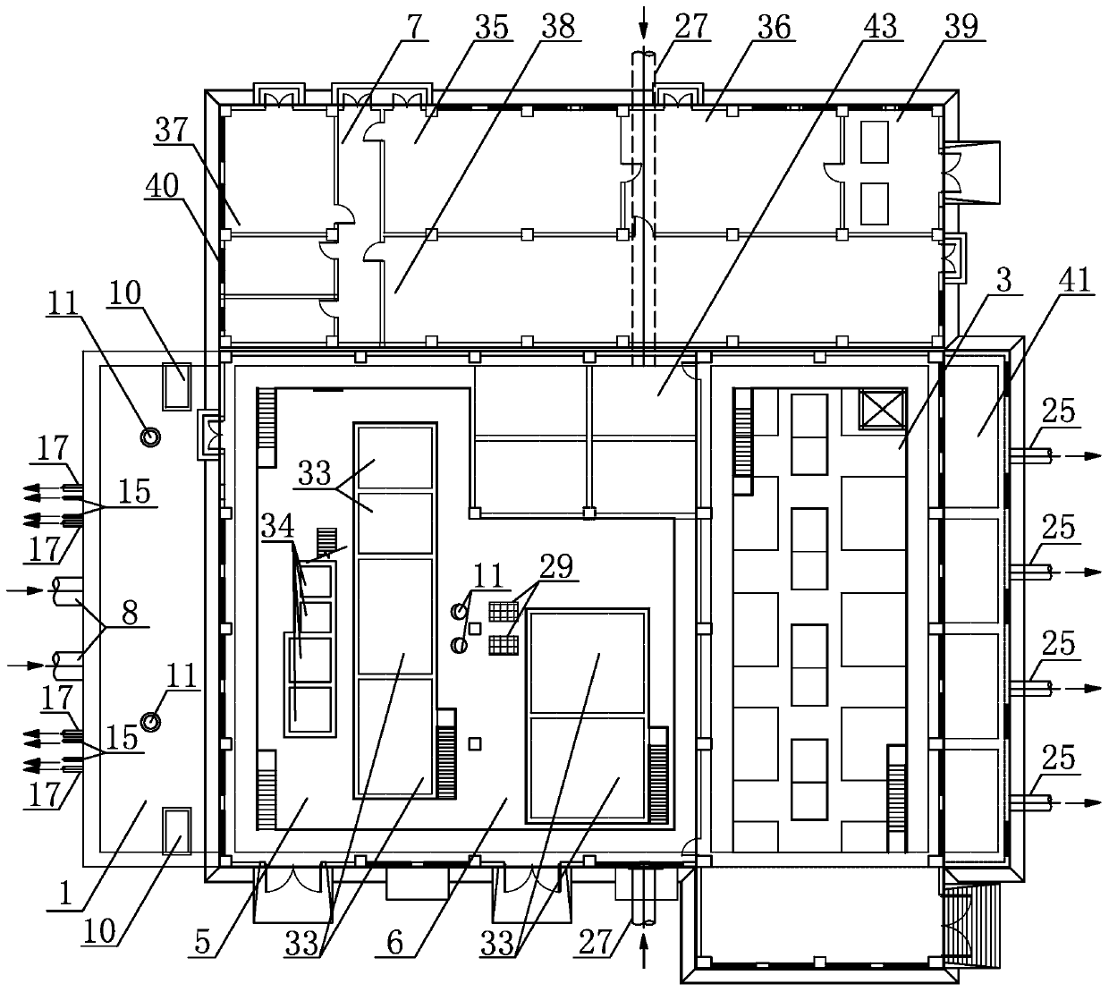
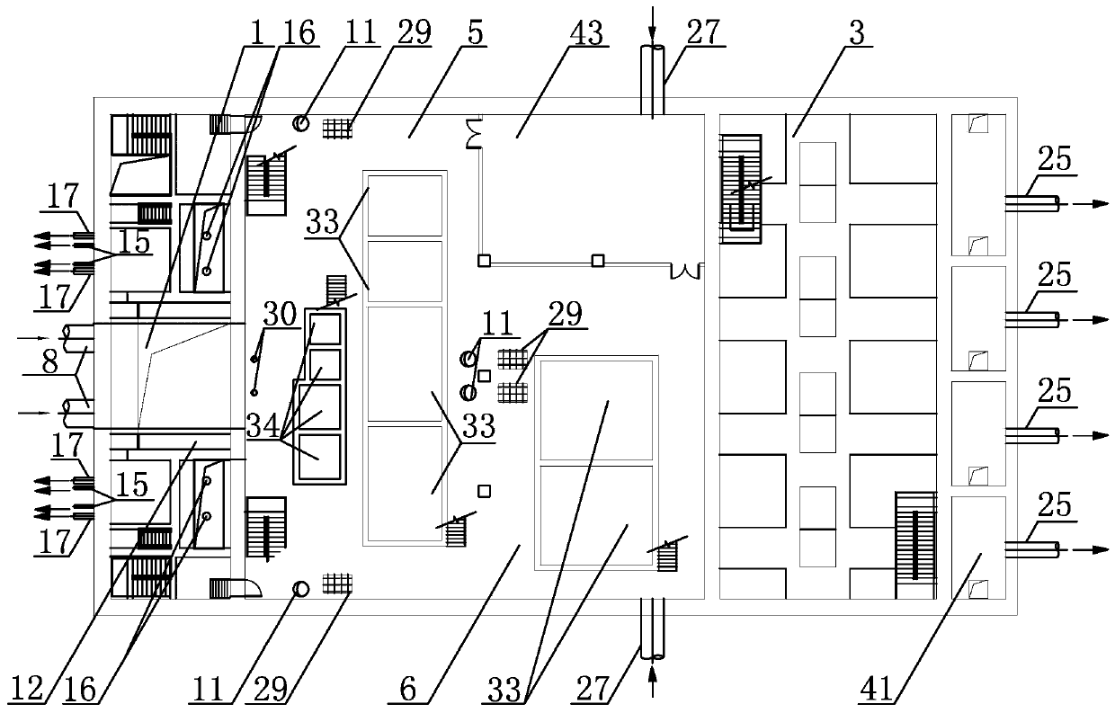
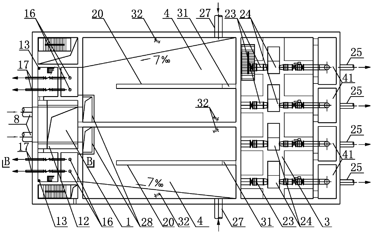
[0044] Refer to each figure, a superimposed group water inlet lifting pump room, including water inlet valve room 1, sump 2, lifting pump room 3, waste water recovery pool 4, sodium hypochlorite pre-dosing room 5 and dosing room 6, distribution Electric room 7;

[0045] see Figure 5 , the water collection pool 2, the waste water recovery pool 4, the sodium hypochlorite pre-dosi...


PUM


Abstract

The invention discloses a superposed group water inlet lifting pump room. The superposed group water inlet lifting pump room comprises a water inlet valve room, a water collecting pond, a lifting pumproom, a wastewater recovery pond, a sodium hypochlorite pre-adding room and dosing room, and an electricity transformation and distribution room; the water collecting pond, the wastewater recovery pond and the sodium hypochlorite pre-adding room and dosing room are in a three-layer superposed arrangement from top to bottom in sequence; the water collecting pond is positioned at the bottommost layer; the wastewater recovery pond is positioned at an intermediate layer; the sodium hypochlorite pre-adding room and dosing room is positioned at the topmost layer; a water inlet valve room and the lifting pump room are respectively arranged at the front end and the rear end of the three-layer superposed structure in sequence; the water collecting pond is partitioned into a front rectifying pond and a rear rectifying pond by arranging a perforated tracery wall in the front section of the water collecting pond; a wastewater recovery pond water inlet pipe is arranged at the tail end of the wastewater recovery pond, and an overflow weir is arranged on the partition wall close to the front end; the sodium hypochlorite pre-adding room and dosing room is arranged above the wastewater recovery pond; the lower part of the water inlet valve room communicates with the water collecting pond; and a horizontal overflow culvert is arranged in the centre of the water inlet valve room. According to the superposed group water inlet lifting pump room, the problem that the land utilization rate of a building which is arranged in areas according to conventional functions can be solved.

Description

technical field [0001] The invention relates to the technical field of engineering construction of a municipal water supply treatment plant, in particular to a superimposed group water inlet lifting pump room. Background technique [0002] In the layout of the water plant, the conventional method is to classify the waterline, mudline, and subsidiary treatment units according to the functional division, and arrange the division plane independently. The land utilization rate is not high, and there is a lack of horizontal comparison and analysis of the design water level process of different types of treatment units. . [0003] Especially when the land occupation of the water plant is limited and the effluent water quality standard is high, when the inflow lift pump room is arranged independently, it is usually realized by reducing the adjustment and storage volume of the sump tank and increasing the start-stop frequency of the lift pump, and the water supply safety is relative...

Claims


Application Information

Patent Timeline
Patent Type & Authority Applications(China)
IPC IPC(8): E03B5/00
CPCE03B5/00
Inventor 罗丁杨力宋奇叵高雷闫京涛张炯田萌陈雪如陈巍孙国志闫朝赵申胡田力常军林欣欣莫剑峰
Owner BEIJING GENERAL MUNICIPAL ENG DESIGN & RES INST
Why Eureka
Try Eureka