

Aero-engine vibration transmission path analysis method based on OTPA method and physical modeling
An aero-engine and vibration transmission technology, which is applied in the direction of internal combustion engine testing, geometric CAD, computer-aided design, etc., can solve the problems of poor guidance, poor consistency of engine vibration data, and no analysis method for the vibration transmission path of the whole aero-engine. , to achieve the effect of improving accuracy, high degree of reduction, and high calculation accuracy
Active Publication Date: 2019-08-27
CIVIL AVIATION UNIV OF CHINA
View PDF8 Cites 2 Cited by
- Summary
- Abstract
- Description
- Claims
- Application Information
AI Technical Summary
Problems solved by technology
[0005]At this stage, the method for analyzing the vibration transmission path of a civil high bypass ratio turbofan engine is limited to the vibration analysis of the local vibration isolation system, without considering the relationship between the various systems inside the engine. Therefore, the consistency of the results obtained with the actual engine vibration data is poor, and a complete analysis method for the vibration transmission path of the aero-engine machine has not been proposed, which has little guidance for solving practical engineering problems. powerful
Method used
View moreImage
Smart ImageViewing Examples

Examples
specific example
[0037] Using the method of the present invention, taking the bearing system rc composed of three bearings rc1, rc2 and rc3 as an example, given the rotor system excitation F 0 sinωt, calculated as Figure 5 As shown in the analysis diagram of the bearing vibration path loss, the average value of the insertion loss of each transmission path can be obtained, ILrc1 = 9.3517; ILrc2 = 4.4158; ILv3 = 4.0301. The contribution of bearing rc1 to the vibration transmission of the receiving end of the system is larger, the contribution of bearing rc2 is the second, and the contribution of bearing rc3 is the smallest. Therefore, bearing rc1 is the main vibration transmission path of the vibration isolation subsystem.
Login to View More PUM
 Abstract
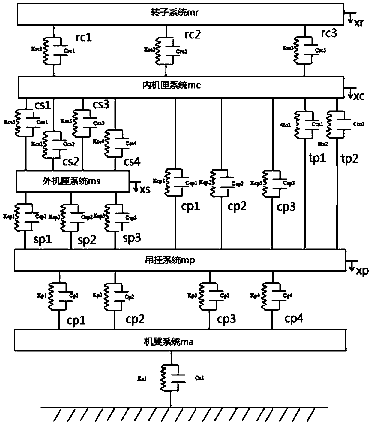
The invention discloses an engine complete machine vibration transmission path analysis method based on an OTPA method and the physical modeling. The method comprises the steps of dispersing an engine into a rotor, a bearing, an inner case, an outer case, a mounting joint, a hanger and a wing system, and enabling the connection among systems to be equivalent to a multi-path vibration isolation system through the OTPA theory; establishing an aero-engine complete machine three-dimensional model; analyzing the three-dimensional model of the aero-engine complete machine; applying the same excitation to different parts of each vibration isolation subsystem, and calculating the responses of receiving ends of different parts; calculating a transfer function matrix of the OTPA method according tovarious working conditions; and judging the contribution of each vibration transmission path to the whole vibration of the aero-engine according to the insertion loss of the vibration path. The method has the advantages that a complete rotor-bearing-casing-mounting joint-hanging-wing dynamic model is established, the vibration energy transmission key paths can be found, and the contribution of the vibration energy in each vibration transmission path can be analyzed.
Description
technical field [0001] The invention belongs to the technical field of aero-engine vibration analysis, in particular to an aero-engine vibration transmission path analysis method based on OTPA and physical modeling. Background technique [0002] The vibration research of aero-engine is one of the important contents of the structural integrity research of aero-engine, and the research on the vibration load transfer path of the whole engine is one of the main ways to improve the performance of the whole engine. For civil large bypass ratio turbofan engines, the research on the vibration transmission path of the whole aircraft engine is of great significance to the structural strength design of the aircraft hanger, the vibration isolation design of the aircraft engine and the noise reduction design of the cabin. [0003] The OTPA method (Operational Transfer Path Analysis) regards the mechanical system as a vibration isolation system composed of a vibration source, a vibration ...
Claims
Login to View More Application Information
Patent Timeline
 Patent Type & AuthorityApplications(China)
IPC IPC(8): G06F17/50G01M15/12
CPCG01M15/12G06F30/15G06F30/20Y02T90/00
Inventor张鸿王俊昌李湘萍崔东泽
OwnerCIVIL AVIATION UNIV OF CHINA