Separating type underwater wellhead suction force anchor in efficient machining and transporting

An underwater wellhead and suction anchor technology, which is applied in wellbore/well components, earthwork drilling, sealing/packing, etc., can solve the problems of oil and gas resource leakage in the formation, the large size of the suction anchor structure, and the inability to produce tightness, etc. To achieve the effect of improving the bearing capacity of the wellhead, reducing the production cost and transportation cost, and reducing the resistance

Pending Publication Date: 2019-08-30
GUANGZHOU MARINE GEOLOGICAL SURVEY
View PDF9 Cites 6 Cited by
  • Summary
  • Abstract
  • Description
  • Claims
  • Application Information

AI Technical Summary

Problems solved by technology

However, the suction anchor used in the exploitation of shallow underwater oil and gas resources must not only provide sufficient vertical load and lateral load, but also need the suction anchor to be in close contact with the formation and have good sealing performance. At the same time, the structure of the suction anchor should be simple and easy to process , manufacturing, and the process of lowering must be safe and reliable. Therefore, the size of the suction anchor structure currently used for the development of underwater oil and gas resources is relatively large, and the structure of the anchor barrel is often deformed or even damaged during land transportation, which greatly increases the development cost. cost
In addition, the suction anchor currently used for the development of underwater oil and gas resources has a large-sized conduit preset inside. In order to ensure the verticality of the conduit and the anchor, ribs are welded at the bottom of the conduit and inside the anchor barrel, so that the suction anchor with the built-in conduit can be placed into the The inside of the anchor barrel behind the formation cannot produce a good seal, which will easily lead to the leakage of formation oil and gas resources and pollute the water environment

Method used


Image

  • Separating type underwater wellhead suction force anchor in efficient machining and transporting
  • Separating type underwater wellhead suction force anchor in efficient machining and transporting
  • Separating type underwater wellhead suction force anchor in efficient machining and transporting

Examples


Embodiment Construction

[0029] The specific implementation manners of the present invention will be further described in detail below in conjunction with the accompanying drawings and embodiments. The following examples are used to illustrate the present invention, but are not intended to limit the scope of the present invention.

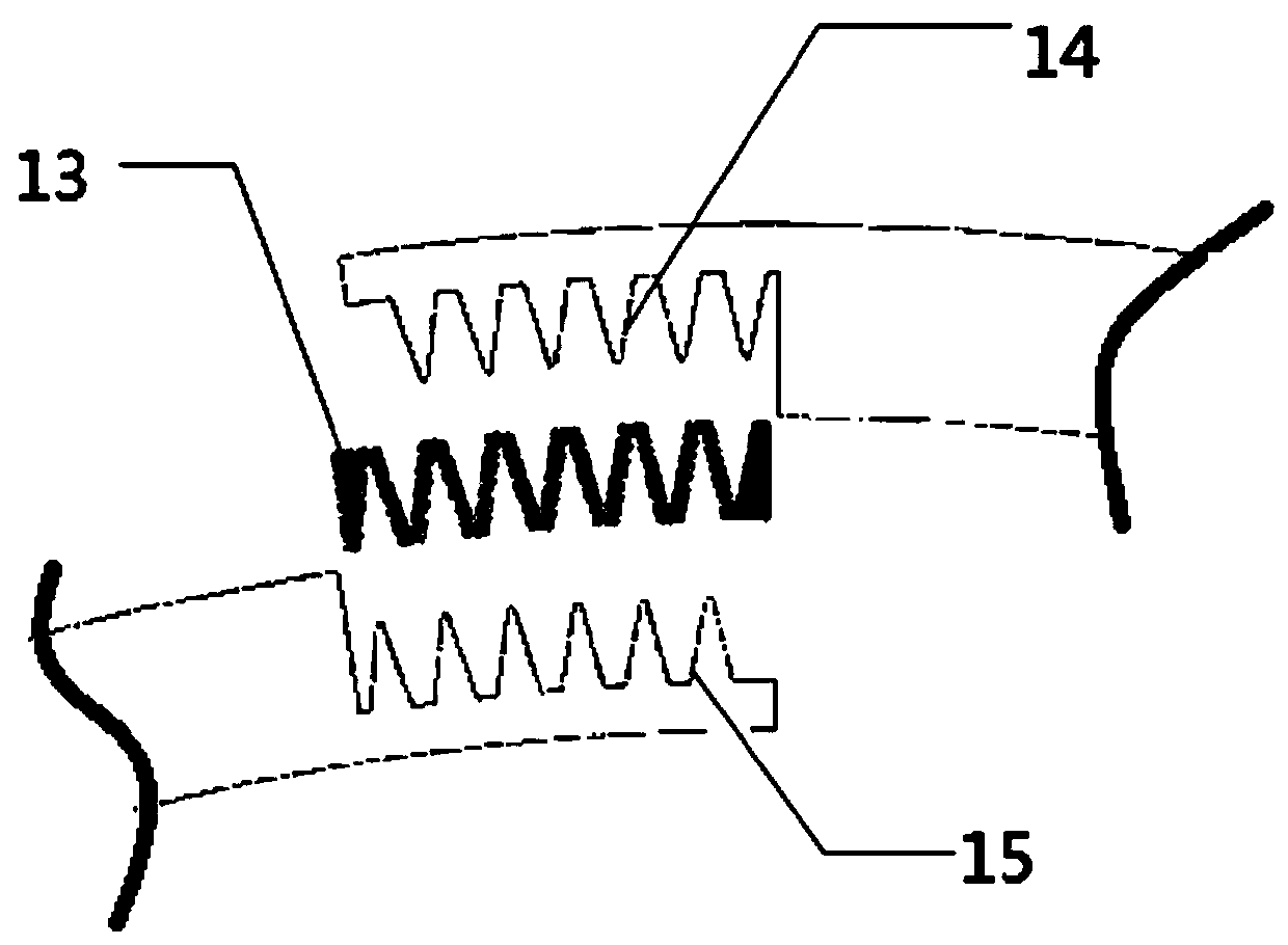
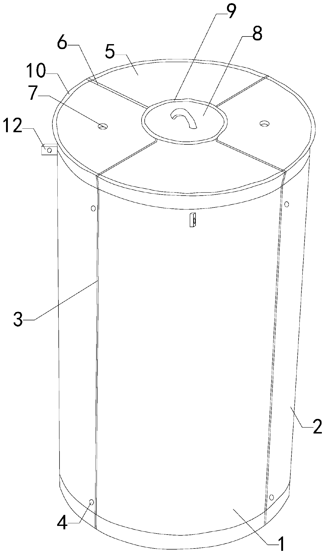
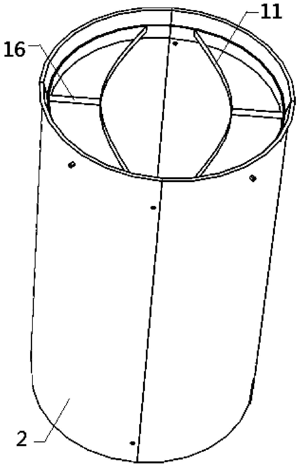
[0030] A separate underwater wellhead suction anchor for high-efficiency processing and transportation of the present invention includes a suction anchor cylinder body 1 with a lower end opening and a top seal. Multiple sets of first rubber strips 3 are used to seal the shells 2 of the anchor shells, and the positioning bolts 4 are used to connect each set of shells 2 of the anchor shells. The top of the shell 1 of the suction anchor is provided with 5 sets of separate sealing covers, and the shells of the anchor shells are The number of the 2 groups is the same as that of the 5 groups of separated sealing covers, and multiple sets of second sealing strips 6 are used to se...


PUM


Abstract

The invention relates to the technical field of ocean engineering accessory devices, in particular to a separating type underwater wellhead suction force anchor in efficient machining and transporting. Disassembling and installing are convenient, the production cost and the transporting cost are lowered, the structural stability and the sealing performance are improved, and a basic guarantee is provided for smoothly building a well. A suction force anchor barrel body with the top of a lower end opening sealed is included; the suction force anchor barrel body comprises separating type anchor barrel plate shell sets; every two adjacent sets of anchor barrel plate shells are sealed through a plurality of first rubber strips; the anchor barrel plate shells in each set are connected through positioning bolts; the top of the suction force anchor barrel body is provided with separating type sealing cover sets; the number of the anchor barrel plate shell sets is equal to that of the separatingtype sealing cover sets; every two adjacent sets of separating type sealing covers are sealed through a plurality of second sealing strips; and the two sets of separating type sealing covers are eachprovided with a water pumping hole.

Description

technical field [0001] The invention relates to the technical field of marine engineering attachments, in particular to a separate underwater wellhead suction anchor for efficient processing and transportation. Background technique [0002] As we all know, the suction cylindrical foundation is a foundation form with good development prospects in marine engineering in the past 20 years. Its inverted cylindrical structure with a closed top and an open bottom is placed in the seabed soil to provide mooring force for ships. It can be used as an infrastructure such as an ocean platform to maintain the stability of the platform. Suction anchors are easy to construct, safe and reliable to use, can be reused, and have better technical and economic characteristics. Therefore, they have received extensive attention from the ocean engineering community and have become a new type of offshore structural facility that is likely to replace the pile structure. [0003] In recent years, wit...

Claims


Application Information

Patent Timeline
Patent Type & Authority Applications(China)
IPC IPC(8): E21B33/043
CPCE21B33/043
Inventor 叶建良寇贝贝谢文卫李彬申凯翔陈靓李晶李博王偲陈静
Owner GUANGZHOU MARINE GEOLOGICAL SURVEY
Why Eureka
Try Eureka