
Test device and test method for bending, fracture and creep of layered rock cantilever

A cantilever bending and creep test technology, applied in the direction of using a stable bending force to test the strength of materials, measuring devices, instruments, etc., can solve the problems of insufficient tensile and pressure stability, unreliable test data, and insufficient test accuracy. Improve test reliability, facilitate long-term use and replacement, and improve measurement accuracy

Inactive Publication Date: 2019-08-30
HEBEI UNIV OF TECH
View PDF10 Cites 7 Cited by
  • Summary
  • Abstract
  • Description
  • Claims
  • Application Information

AI Technical Summary

Problems solved by technology

[0003] The characteristic of the rock creep test is that the pressurization device should provide a constant pressure. Most of the current rock creep test devices use rigid hydraulic servo testing machines for loading, such as the documents published in the application numbers 201610485397.7 and 200910065577.X. Although these instruments The device has superior performance in load control and data acquisition, but it also has obvious disadvantages: first, the loss of equipment during the test is large, and the test cost is high; second, the stability of the tension and pressure loaded by the servo system is not enough, resulting in insufficient test accuracy
For the hydraulic servo loading method of the mechanical test press, an electric oil pump is used to pressurize the test piece. It is difficult for such a press to ensure the stable working performance of the oil pump during the loading process of dozens of days, resulting in unstable pressure during the test. The test data is unreliable
In particular, it should be pointed out that most of the existing test devices involved in rock creep tests are rock creep tests under tension or compression, and few test devices involve rock cantilever bending creep tests.

Method used


Image

  • Test device and test method for bending, fracture and creep of layered rock cantilever
  • Test device and test method for bending, fracture and creep of layered rock cantilever
  • Test device and test method for bending, fracture and creep of layered rock cantilever

Examples


Embodiment 1

[0067] Step 1. Preparation of the rock specimen to be tested:

[0068] (1) Cut the red sandstone block to be tested into a rectangular plate rock specimen of regular shape required for the test. The specimen size is 1750mm×300mm×150mm, and its natural weight is 25kN / m 3 .

[0069] (2) Grinding the surface of layered rock specimen 18, and then performing speckle image processing on its side surface, to provide reference points for DIC imaging technology in the test process;

[0070] Step 2. Installation of the test device:

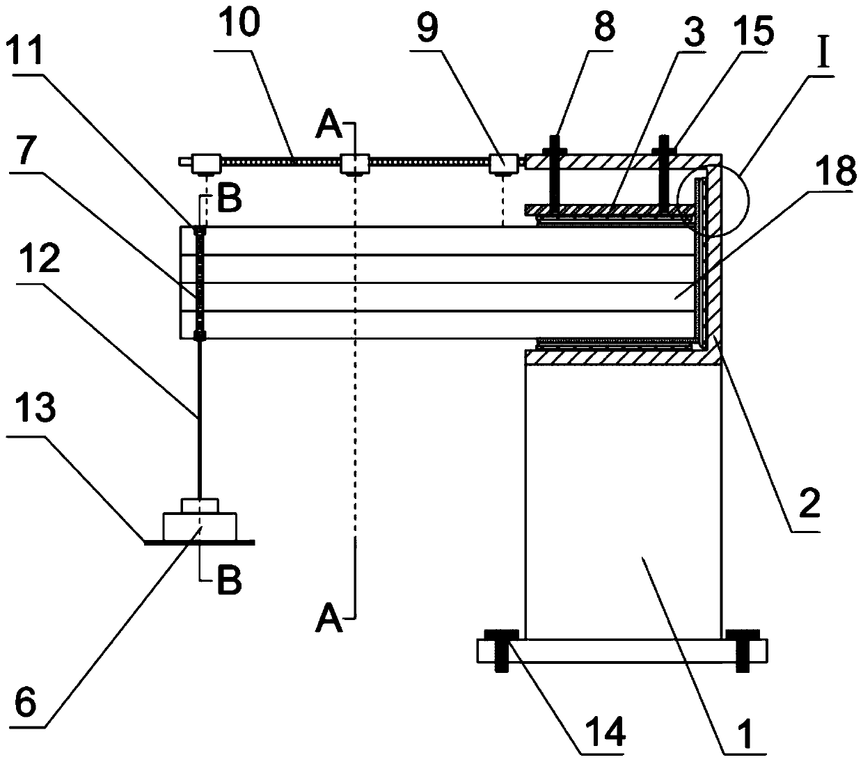
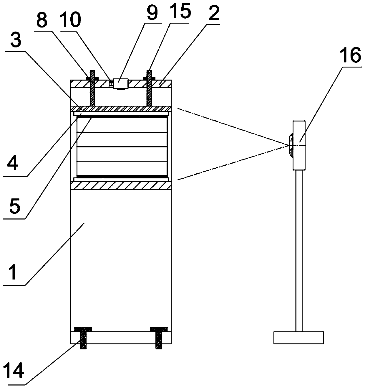
[0071] (1) One end of the layered rock test piece 18 of step 1 is put into the reaction force frame 2, so that one end of the layered rock test piece 18 is closely fitted with the flexible cushion layer 5 on the inner side of the bottom of the reaction force frame and the inner side of the side; then The flexible cushion 5 is placed between the limiting plate 3 and the layered rock test piece 18, and the limiting plate 3 is lowered to a suitable height by...


PUM

PropertyMeasurementUnit
thicknessaaaaaaaaaa
flexural strengthaaaaaaaaaa

Abstract

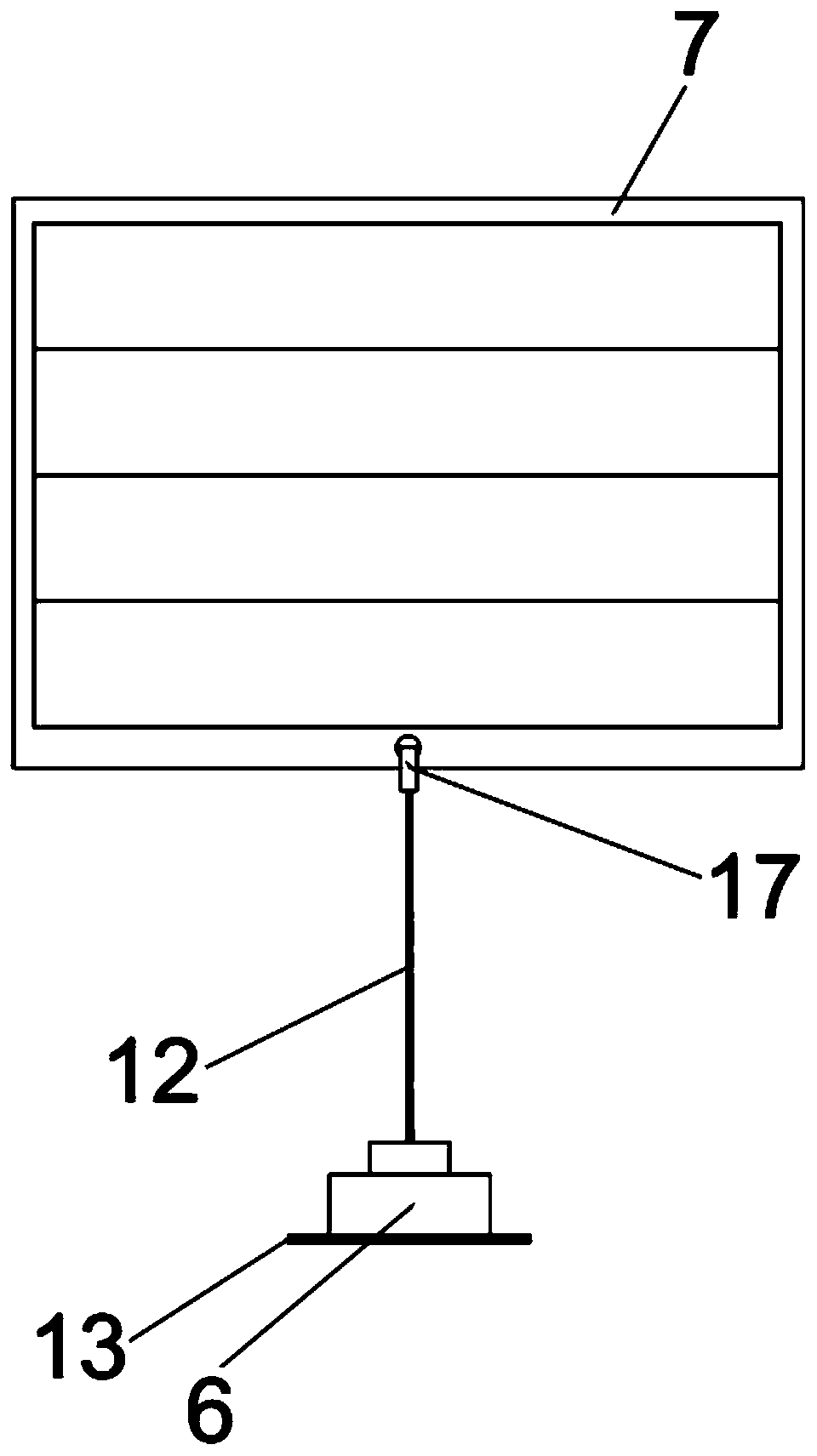
The invention discloses a test device and a test method for the bending, fracture and creep of a layered rock cantilever. The device comprises a fixed support base, a counterforce frame, a limiting plate, a roller device, a flexible cushion layer, a weight, a connector, a screw, a non-contact displacement meter, a horizontal guide rail and non-contact strain field test equipment. By using the device, the long-term bending, fracture and creep test research of the cantilever of the rock material can be achieved, so that the long-term bending strength, deformation fracture evolution law, fracturemechanical mechanism and the like of the rock and the layered rock are acquired, and a theoretical support is provided for the long-term stable assessment on the bending and damage of the engineeringrock cantilever. The device has the advantages of convenient test operation and high measurement accuracy, meanwhile, the device is simple and reasonable in structure, small in instrument loss, low in test cost, and capable of meeting the bending and creep test requirements of the layered rock. The method is simple, quick, and accuracy to measure.

Description

technical field [0001] The invention relates to the field of rock and soil mechanical performance testing, in particular to a cantilever bending fracture creep test device and a test method for a layered rock mass. Background technique [0002] Layered rock mass is one of the main occurrence forms of rock in nature, and it is common in large-scale hydropower project areas in the west of my country, especially in the high and steep canyon mountainous areas in the southwest. The toppling and instability process of layered rock mass slopes often has complex evolution processes such as interlayer shear dislocation, intralayer bending-tension cracking, intralayer tension-shear failure, and fracture-falling failure. Under the long-term action of gravity, this process has a long timeliness before the overall destruction. In addition, due to the differences in rock mechanical properties between layered rock layers, the deformation and failure are strongly inconsistent, which makes ...

Claims


Application Information

Patent Timeline
Patent Type & Authority Applications(China)
IPC IPC(8): G01N3/20G01N3/06G01N3/04
CPCG01N3/04G01N3/068G01N3/20G01N2203/0023G01N2203/0067G01N2203/0071G01N2203/0282G01N2203/0641G01N2203/0647
Inventor 黄达黄文波裴向军宋宜祥岑夺丰
Owner HEBEI UNIV OF TECH
Learn More