Distributed power line fault positioning system and method based on wave velocity dynamic measurement of traveling waves

A distributed power and dynamic measurement technology, applied in the direction of measuring electricity, fault location, measuring electrical variables, etc., can solve problems such as poor accuracy, weak signal, and limited use conditions, so as to improve measurement accuracy and accuracy, attenuation and distortion The effect of reducing the degree and improving the positioning accuracy

Pending Publication Date: 2019-08-30
CHENGDU ZHONGGONG TECH
View PDF0 Cites 16 Cited by
  • Summary
  • Abstract
  • Description
  • Claims
  • Application Information

AI Technical Summary

Problems solved by technology

The biggest problem with the offline ranging method is that some cable sintering faults are often difficult to reproduce under the impact of high-voltage pulses, resulting in the failure of fault location with high-voltage pulse injection in this offline situation.
The disadvantage of this method is: the strength of the current signal flowing into the ground is related to the power of the voltage transformer PT, the smaller the power, the weaker the signal, and it is difficult to track; when the excessive resistance is large, due to the effect of distributed capacitance, the current signal flowing into the ground will The current generates a shunt, which further weakens the strength of the current signal; if an arc is generated at the grounding point, the current signal flowing into the ground will no longer have the characteristics of continuity, so it is difficult to trace its trace, which makes this method invalid
[0022] Judging from the existing fault traveling wave velocity measurement methods, the traditional methods are either less accurate or have limitations in use conditions

Method used


Image

  • Distributed power line fault positioning system and method based on wave velocity dynamic measurement of traveling waves
  • Distributed power line fault positioning system and method based on wave velocity dynamic measurement of traveling waves
  • Distributed power line fault positioning system and method based on wave velocity dynamic measurement of traveling waves

Examples


Embodiment Construction

[0054] The technical solutions of the present invention will be clearly and completely described below in conjunction with the embodiments. Apparently, the described embodiments are only some of the embodiments of the present invention, not all of them. Based on the embodiments of the present invention, all other embodiments obtained by those skilled in the art without making creative efforts belong to the protection scope of the present invention.

[0055] A distributed power line fault location method based on dynamic measurement of traveling wave velocity, including the following steps:

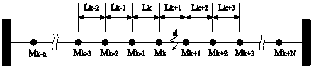
[0056] S1: if figure 1 As shown in , multiple fault traveling wave distance measuring devices are arranged distributedly on the power line, and they are respectively installed in the M k-n ,...,M k-2 , M k-1 , M k , M k+1 , M k+2 ,...,M k+N point;

[0057] S2: The grounding or short circuit fault occurs at point d, and the traveling wave generated by the fault propagates to the lef...


PUM


Abstract

The invention discloses a distributed power line fault positioning system and method based on wave velocity dynamic measurement of traveling waves. A hand-in-hand distributed system architecture is adopted, in the case that the system has no central master station, when a certain measurement point cannot work normally, the system can still position a fault normally due to the multi-end redundant design, so that the reliability of the system is improved. The independently operating ranging devices can know the operation states and measurement results of other related devices, the measurement result of the present device can be verified, the positioning accuracy of the present device is improved, and the fault / abnormal node can be quickly discovered through mutual verification. Moreover, dueto the application of the hand-held distributed system architecture, bad data having great influence on the accuracy can be filtered and eliminated, and then the measurement precision and accuracy ofthe system are further improved. The actual wave velocity of traveling waves generated by the present fault is measured in real time by using the same type of power wires or power cables in an adjacent area of the fault point, thereby further improving the accuracy of positioning and ranging.

Description

technical field [0001] The invention relates to a fault location method of a power line, in particular to a distributed power line fault location system and method based on dynamic measurement of traveling wave velocity. Background technique [0002] 10kV automatic blocking and continuous transmission line (Automatic blocking and continuous transmission line) and cables refer to important transmission lines connecting two adjacent substations and power distribution stations along the railway line, and are responsible for supplying power to stations, section loads and signal equipment along the line important task. Together with railway substations and power distribution stations, it forms a special power supply system for railways. The railway self-closing through line is in a complex and changeable environment, and various types of failures are relatively prone to occur. Among them, permanent failures that are difficult to troubleshoot pose the greatest threat to railway o...

Claims


Application Information

Patent Timeline
Patent Type & Authority Applications(China)
IPC IPC(8): G01R31/08
CPCG01R31/085G01R31/088
Inventor 陈东洲赵宁周劲松袁云祥杨军黄稚斌雷汛
Owner CHENGDU ZHONGGONG TECH
Why Eureka
Try Eureka