Spread spectrum technology-based laser radar ranging method and device

A technology of laser radar and technology, which is applied in the direction of measuring device, electromagnetic wave re-radiation, radio wave measuring system, etc., can solve the problems of sensitive linearity of measurement accuracy, slow speed, large volume of laser light source, etc., to improve the measurement speed, Strong ability to dry out external interference and cheap price

Active Publication Date: 2019-08-30
李思佳
View PDF9 Cites 7 Cited by
  • Summary
  • Abstract
  • Description
  • Claims
  • Application Information

AI Technical Summary

Problems solved by technology

The main disadvantages of FMCW are: firstly, the FMCW laser source is bulky and expensive, and secondly, it requires more computing power, so it is slower in generating a full 3D surround map, and the measurement accuracy is very critical to the degree of linearity in modulation. sensitive
The difference in beam diameter will lead to completely different phase modulation methods. For example, it is very easy to select a device with a half-wave voltage of a few volts for a fiber phase modulator. If the phase modulation is performed on a beam whose beam diameter reaches centimeters, the half-wave voltage will Dozens of times or even hundreds of thousands of times increase, which will make the modulation method used in the optical fiber phase modulator unchanged, and in some cases it is difficult to use it in the laser radar

Method used


Image

  • Spread spectrum technology-based laser radar ranging method and device
  • Spread spectrum technology-based laser radar ranging method and device
  • Spread spectrum technology-based laser radar ranging method and device

Examples


Embodiment 1

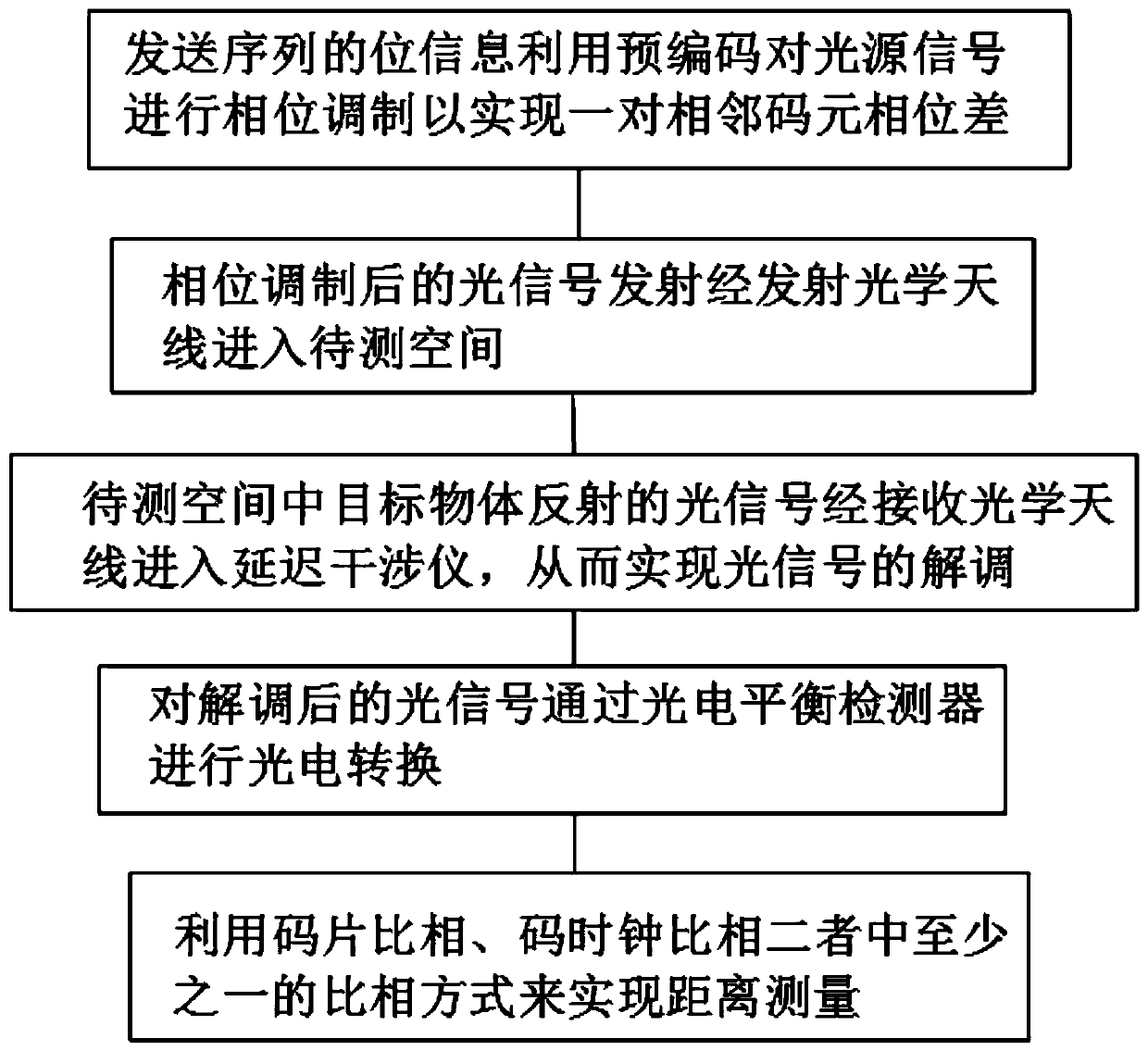
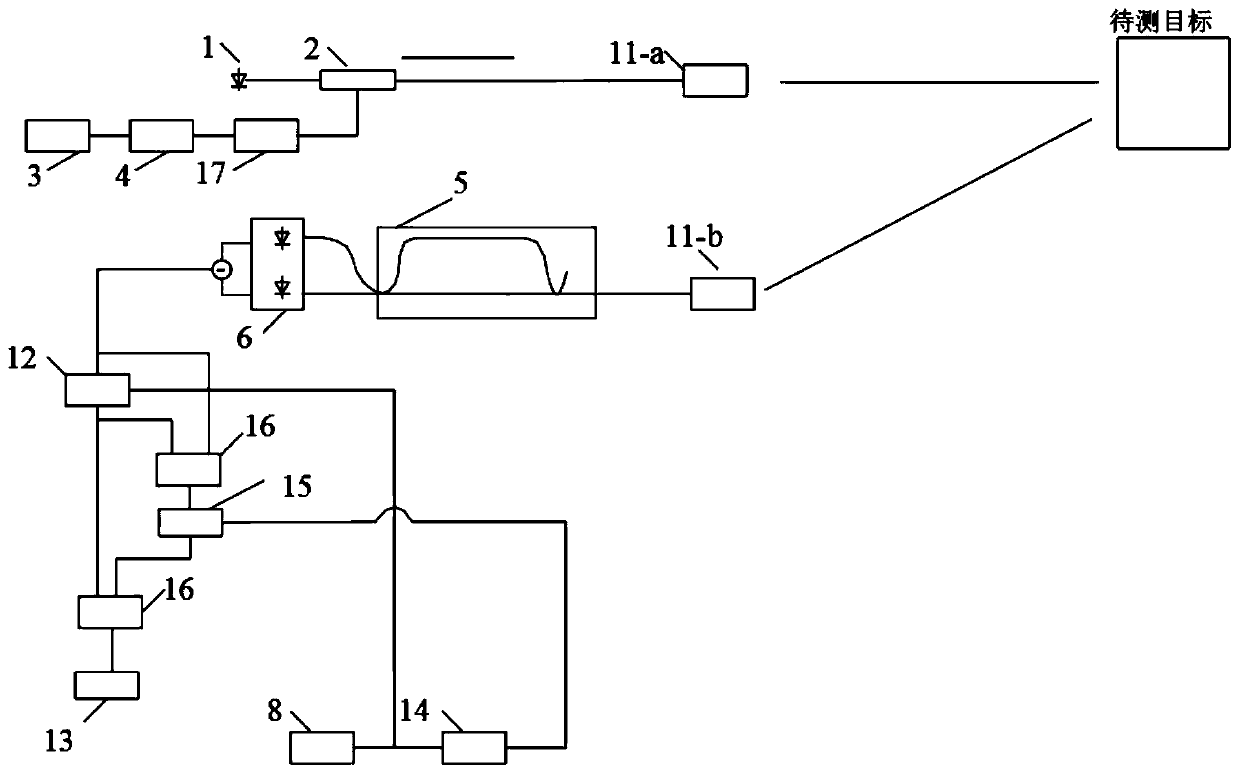
[0081] see figure 2 , the present invention provides a technical solution: a method for laser radar ranging based on spread spectrum technology, comprising the following steps:

[0082] S1: The bit information of the transmission sequence uses a pair of adjacent symbol phase differences to perform phase modulation on the light source signal to achieve a pair of adjacent symbol phase differences. The transmission sequence uses composite codes to reduce the acquisition time of correlation despreading. Specifically include The following steps:

[0083] A: The optical sending unit 1 generates a light source signal;

[0084] B: The send sequence generator generates a send sequence signal;

[0085] C: the precoder 4 precodes the transmission sequence bit signal in the above step B to generate a pair of adjacent symbol phase differences;

[0086] D: The phase modulation driver 17 converts the digital signal into a corresponding level signal to complete the driving of the first ph...

Embodiment 2

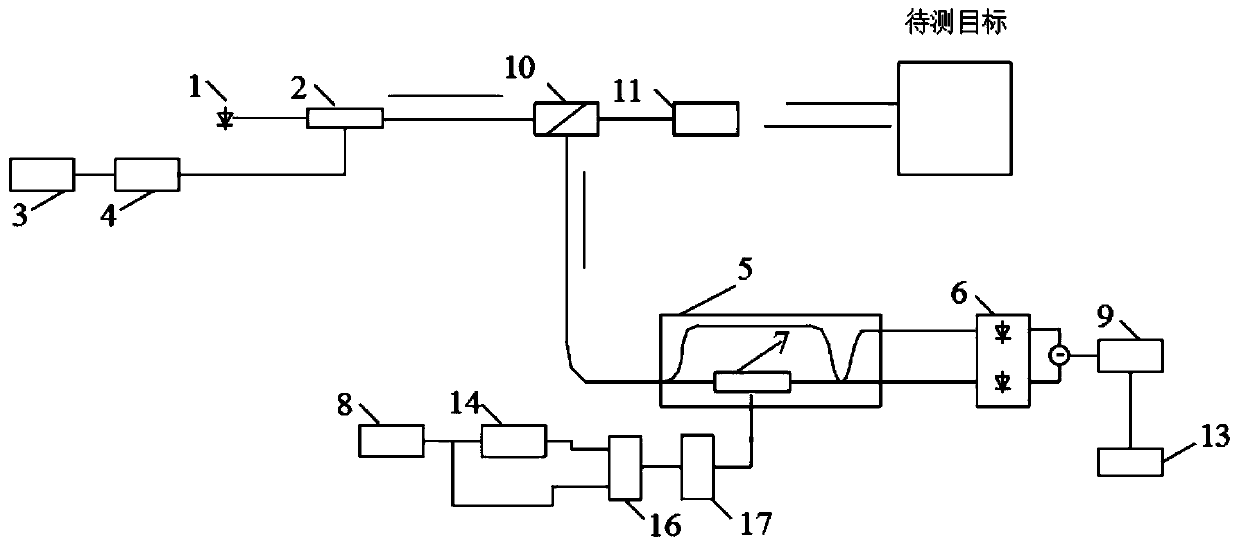
[0096] see image 3 , the present invention provides a technical solution: a method for laser radar ranging based on spread spectrum technology, comprising the following steps:

[0097] S1: The bit information of the transmitted sequence uses a pair of adjacent symbol phase differences to perform phase modulation on the light source signal to achieve a pair of adjacent symbol phase differences. The transmitted sequence uses composite codes to reduce the acquisition time of correlation despreading. Specifically Include the following steps:

[0098] A: The optical sending unit 1 generates a light source signal;

[0099] B: The send sequence generator generates a send sequence signal;

[0100] C: the precoder 4 precodes the transmission sequence bit signal in the above step B to generate a pair of adjacent symbol phase differences;

[0101] D: The phase modulation driver 17 converts the digital signal into a corresponding level signal to complete the driving of the first phase...


PUM


Abstract

The invention discloses a spread spectrum technology-based laser radar ranging method and device, and belongs to the field of laser radar ranging. The method comprises the following steps of S1, enabling bit information of a transmission sequence to carry out phase modulation on a light source signal by utilizing a phase difference between a pair of adjacent code elements; S2, enabling the phase-modulated light signal to enter a to-be-measured space through a transmission optical antenna; S3, enabling the reflected light signal to enter a delay interferometer so as to realize the demodulationof the light signal; S4, carrying out photoelectric conversion on the demodulated light signal through a photoelectric balance detector; and S5, enabling a local sequence to realize range measurementby utilizing at least one phase comparison manner of code chip phase comparison and code clock phase comparison. Based on a spread spectrum technology, the laser radar ranging method and device are strong in external interference resistance, long in detection distance and low in cost, and are capable of carrying out rough measurement or accurate measurement according to practical requirements so as to improve the measurement speed.

Description

technical field [0001] The invention relates to the field of laser radar distance measurement, in particular to a laser radar distance measurement method based on spread spectrum technology. [0002] The invention relates to the field of laser radar distance measurement, in particular to a laser radar distance measurement device based on spread spectrum technology. Background technique [0003] As a sensor that can obtain information about the position and shape of objects, lidar is suitable for terrain mapping. It is often used in indoor modeling, data collection of roads and facilities, mine goaf measurement, or carried on aircraft for large-scale power line inspection, forestry census, water conservancy survey, etc., and has a wide range of applications. At present, the application of lidar measurement technology is showing a diversified trend. In addition to traditional surveying and mapping, it has shown broad market prospects in emerging industries such as unmanned dr...

Claims


Application Information

Patent Timeline
Patent Type & Authority Applications(China)
IPC IPC(8): G01S17/08G01S7/483
CPCG01S17/08G01S7/483
Inventor 李思佳陈雯柏齐跃峰李卫
Owner 李思佳
Why Eureka
Try Eureka