Waveguide power splitter

A power divider and waveguide technology, applied in the field of microwave and millimeter wave circuits, can solve the problems of output port arm length, large area occupation, non-planar output port, etc., and achieve the effect of improving isolation and compact structure

Pending Publication Date: 2019-08-30
CETC GUOJI SOUTHERN GRP CO LTD
View PDF0 Cites 5 Cited by
  • Summary
  • Abstract
  • Description
  • Claims
  • Application Information

AI Technical Summary

Problems solved by technology

But they all have three common shortcomings: the first is that the output port is non-planar
The second disadvantage is that a part of the coupling probe used to improve the isolation measures is exposed, and when the circuit is applied to the system, it will occupy a large area, resulting in a bloated system structure
The third disadvantage is that the output port adopts the form of waveguide ladder impedance, which will make the arms of the two output ports longer, which is not conducive to the miniaturization of the circuit.

Method used


Image

  • Waveguide power splitter
  • Waveguide power splitter
  • Waveguide power splitter

Examples


Embodiment 1

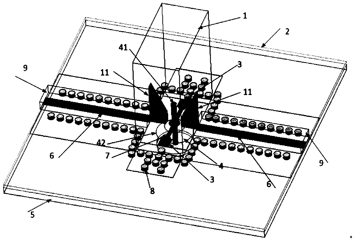
[0028] The present invention will be further described below in conjunction with accompanying drawing and specific embodiment: figure 1 Shown is a schematic diagram of a waveguide power splitter operating at 35 GHz. The power divider includes a section of waveguide 1 , a section of dielectric substrate 2 etched with a planar circuit, two isolation resistors 3 , a glass insulator 4 and a supporting metal plate 5 . The dielectric substrate 2 is arranged on the metal plate 5, the waveguide 1 is arranged on the dielectric substrate 2, the size of the waveguide 1 (the cavity surrounded by the waveguide transmission line) is 3.556mm×7.112mm, and the two ridge waveguides 11 are symmetrically arranged on the The waveguide 1 is internally connected vertically to the dielectric substrate 2, and the ridge waveguide 11 is in the form of a trapezoidal ridge waveguide; the waveguide 1 is located at the geometric center of the dielectric substrate 2, and a microstrip line 7 is arranged betwe...


PUM


Abstract

The invention discloses a waveguide power splitter. The waveguide power splitter includes a waveguide, a dielectric substrate etched with a planar circuit, two isolation resistors, a glass insulator and a metal plate for fixing. Through properly designing the size of the circuit, the circuit can perform the function of power division. The test result shows that when the waveguide power splitter isin the range of 34.6-39 GHz, echo loss is greater than 15 dB, overall circuit insertion loss is less than 4 dB, and the isolation degree is greater than 20 dB. The waveguide power splitter can be applied to a microwave millimeter wave communication system, and properties of compact structure, high isolation, output port planarization and easy integration with other planar circuits are achieved.

Description

technical field [0001] The invention relates to the field of microwave and millimeter wave circuits, in particular to a waveguide power divider. Background technique [0002] The power divider is a key circuit in modern wireless communication systems such as radar and satellite communication, and its performance plays a vital role in the entire wireless system. According to the realization form of the power divider, the power divider can be divided into a microstrip power divider and a waveguide power divider. Because of its planar structure, the power divider of microstrip structure is easy to process and realize, and has been widely used in microwave circuits in recent years. However, with the increase of operating frequency, the insertion loss of the power splitter based on the microstrip structure is getting larger and larger, which is difficult to meet the requirements of the system. The waveguide power splitter is still widely used in the millimeter wave frequency ba...

Claims


Application Information

Patent Timeline
Patent Type & Authority Applications(China)
IPC IPC(8): H01P5/12
CPCH01P5/12
Inventor 唐聪潘晓枫
Owner CETC GUOJI SOUTHERN GRP CO LTD
Why Eureka
Try Eureka