
Narrow pulse driving system and method for pulse laser

A technology of pulsed lasers and driving systems, which is applied to lasers, devices for controlling laser output parameters, laser components, etc., can solve the problems of complicated debugging process, difficult to obtain narrow pulses, difficult to control pulse amplitude, etc., to reduce dissipation The effect of good power and pulse stability and easy adjustment

Pending Publication Date: 2019-08-30
苏州贝林激光有限公司
View PDF0 Cites 5 Cited by
  • Summary
  • Abstract
  • Description
  • Claims
  • Application Information

AI Technical Summary

Problems solved by technology

However, the quality of laser pulses mainly depends on the performance of the driving power supply. The traditional driving circuit mainly uses avalanche tubes and RC elements to achieve narrow pulses, or uses metal oxide semiconductor field effect transistors (MOS transistors) and RC elements to play the role of switching devices. Narrow pulses can be obtained by charging and discharging under the same conditions, but the disadvantages of both are that due to the influence of circuit board parasitic parameters, narrow pulses are not easy to obtain, the debugging process is complicated, and the pulse amplitude is difficult to control

Method used


Image

  • Narrow pulse driving system and method for pulse laser
  • Narrow pulse driving system and method for pulse laser

Examples


Embodiment Construction

[0027] The following will clearly and completely describe the technical solutions in the embodiments of the present invention with reference to the accompanying drawings in the embodiments of the present invention. Obviously, the described embodiments are only some, not all, embodiments of the present invention. The components of the embodiments of the invention generally described and illustrated in the figures herein may be arranged and designed in a variety of different configurations. Accordingly, the following detailed description of the embodiments of the invention provided in the accompanying drawings is not intended to limit the scope of the claimed invention, but merely represents selected embodiments of the invention. Based on the embodiments of the present invention, all other embodiments obtained by those skilled in the art without making creative efforts belong to the protection scope of the present invention.

[0028] It should be noted that like numerals and let...


PUM


Abstract

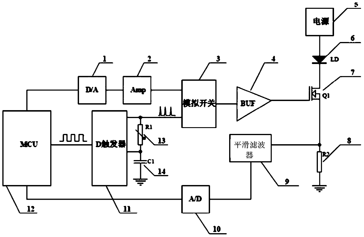
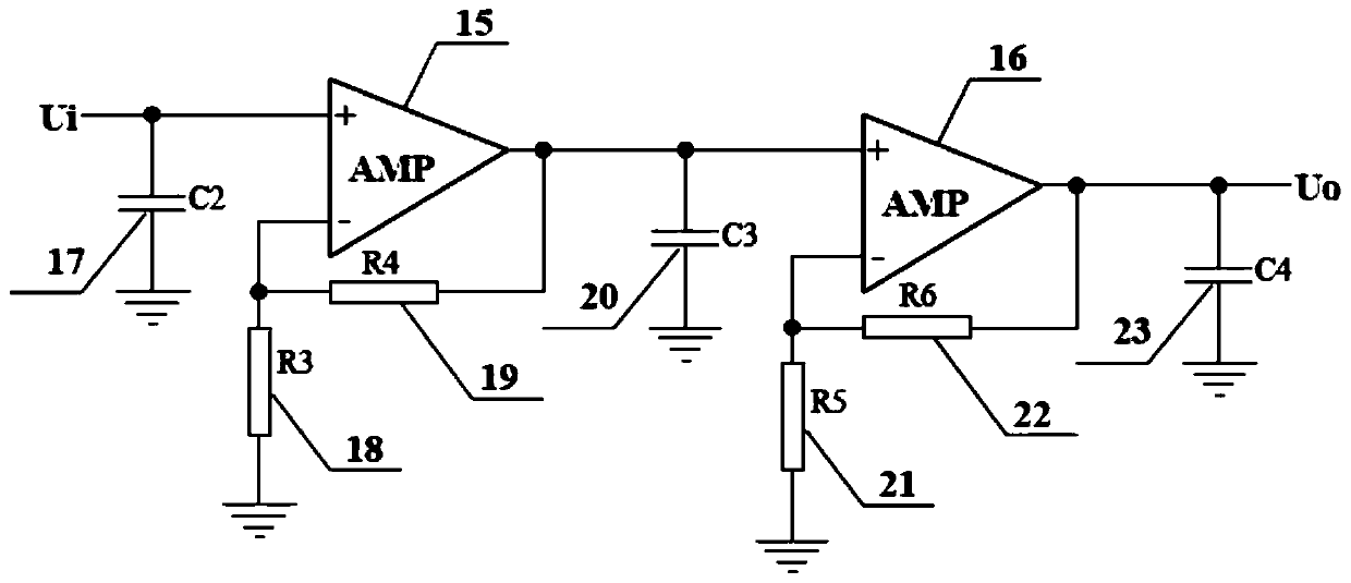
The invention relates to a narrow pulse driving system and method for a pulse laser. A digital output port of a micro-control unit is connected with a digital input port of a digital-to-analog converter, the clock output port of the micro-control unit is connected with a clock input port of a D trigger, the zero clearing end of the D trigger is connected with a capacitor 1 and an adjustable resistor 1, and the output end of the D trigger is connected with the adjustable resistor 1 and the enabling end of an analog switch, the analog output end of the digital-to-analog converter is connected with the positive input end of an operational amplifier, the output end of the operational amplifier is connected with the analog input end of the analog switch, the output end of the analog switch is connected with an input end of an analog buffer, the output end of the analog buffer is connected with the grid electrode of an MOS tube, the source electrode of the MOS tube is connected with a sampling resistor 2, the drain electrode of the MOS tube is connected with the negative pole of a laser diode, the positive pole of the laser diode is connected with a power supply, the sampling resistor 2is in signal connection with the input end of a smooth filter, the output end of the smooth filter is connected with the analog input port of an analog-to-digital converter, and the digital output port of the analog-to-digital converter is connected with the digital input port of the micro-control unit. The regulation is simple, and the stability of laser pulse generated by driving is good.

Description

technical field [0001] The invention relates to a narrow pulse driving system of a pulse laser and a method thereof. Background technique [0002] At present, laser pulses using semiconductor lasers are widely used in optical communication, ranging and medicine, and the rise time of laser pulses has a great relationship with measurement accuracy. The narrower the pulse, the higher the signal-to-noise ratio. However, the quality of laser pulses mainly depends on the performance of the driving power supply. The traditional driving circuit mainly uses avalanche tubes and RC elements to achieve narrow pulses, or uses metal oxide semiconductor field effect transistors (MOS transistors) and RC elements to play the role of switching devices. Narrow pulses can be obtained by charging and discharging under the same conditions, but the disadvantages of both are that due to the influence of parasitic parameters of the circuit board, narrow pulses are not easy to obtain, the debugging p...

Claims


Application Information

Patent Timeline
IPC IPC(8): H01S5/042H01S5/06
CPCH01S5/0428H01S5/06
Inventor 赵裕兴许卫星李立卫
Owner 苏州贝林激光有限公司
Learn More