

Steel pipe bend cutting device
A cutting device and elbow technology, applied in welding equipment, laser welding equipment, metal processing equipment, etc., can solve the problems of poor quality, low cutting accuracy, and difficulty in grinding the cutting angle of the elbow, so as to achieve high control accuracy, cutting High precision and good cutting effect
- Summary
- Abstract
- Description
- Claims
- Application Information
AI Technical Summary
Problems solved by technology
Method used
Image

Examples
Embodiment 1
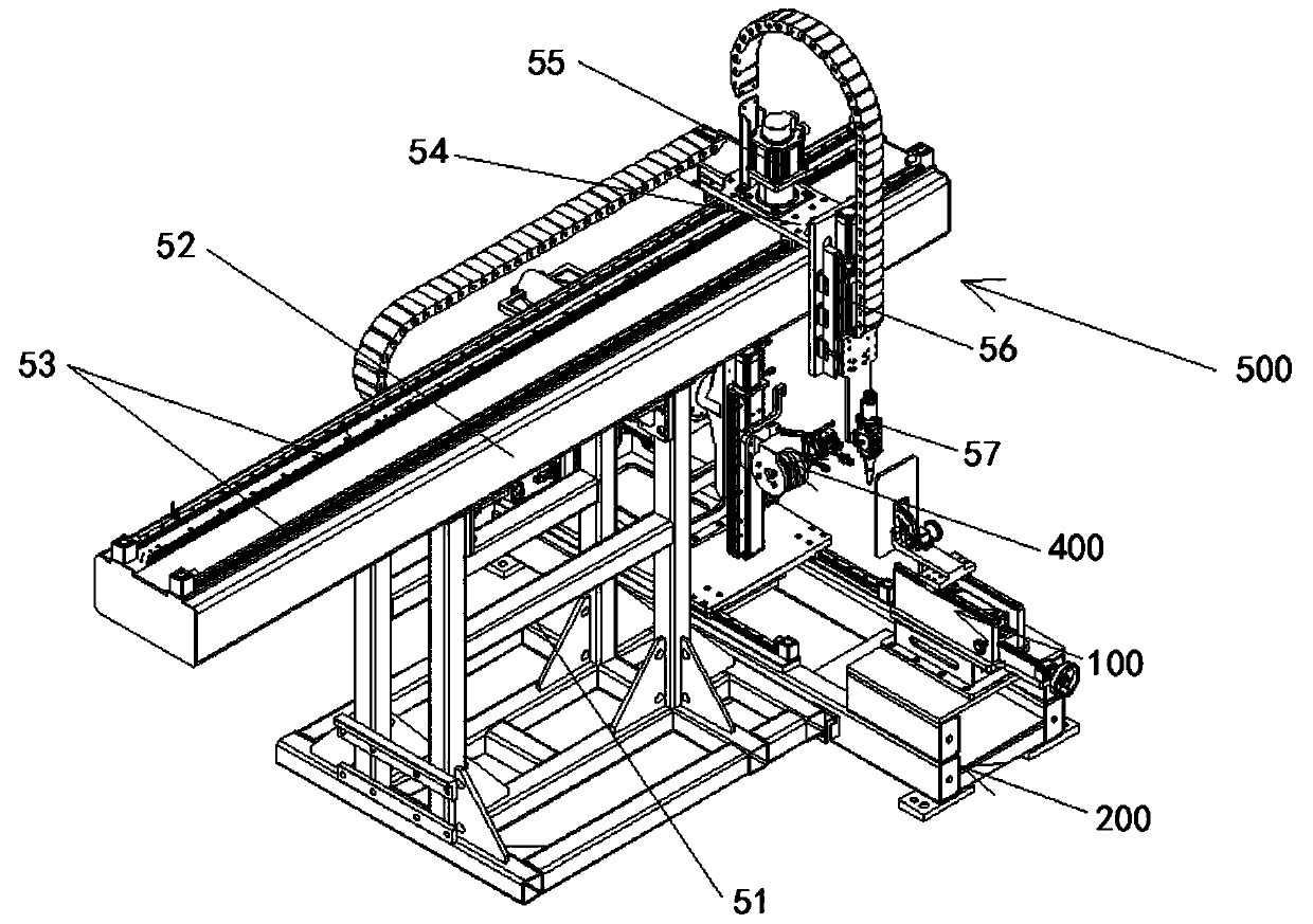
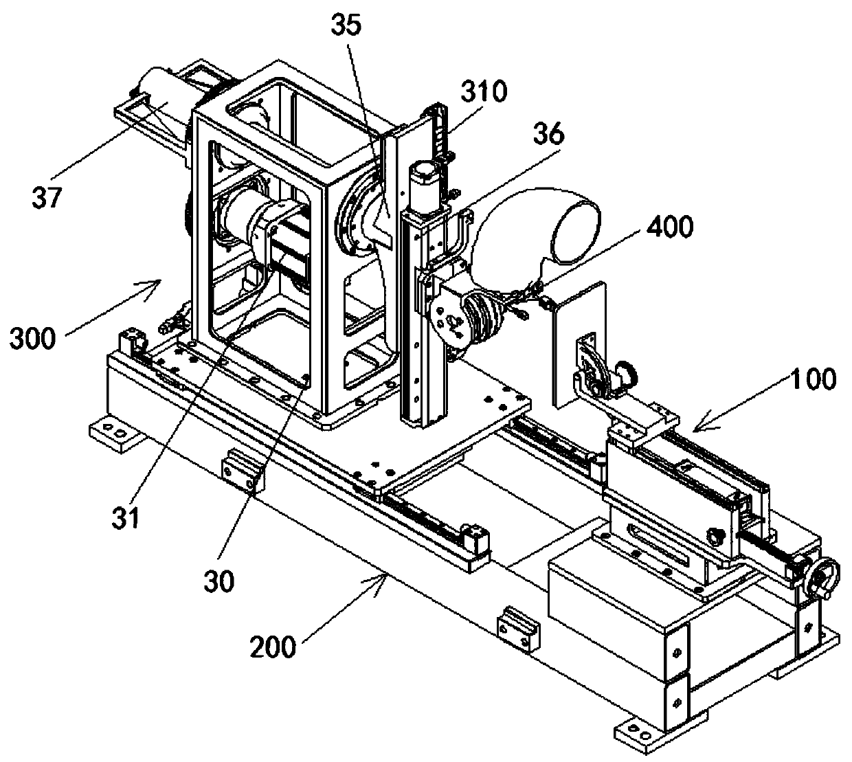
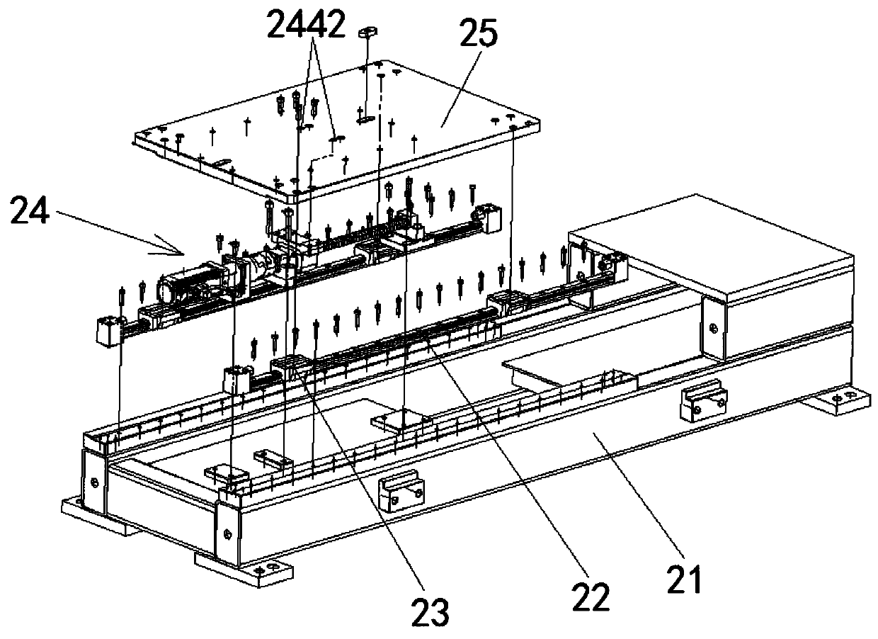
[0045] like Figures 1 to 7 As shown, the embodiment of the present invention provides a steel pipe elbow cutting device, which specifically includes a sliding base assembly 200, an elbow spindle installation assembly 300, an indexing system 400, and a laser cutting assembly 500; the elbow spindle installation assembly 300 Installed on the sliding base assembly 200, the elbow spindle installation assembly 300 is driven by the sliding base assembly 200 to move linearly in the horizontal direction. The indexing system 400 is connected with the elbow spindle installation assembly 300, and the elbow spindle installation assembly 300 is used to drive the indexing system 400 to move in a straight line in the vertical direction and at the same time perform the bending of the elbow during the steel pipe elbow cutting process. For rotary cutting, the indexing system 400 is used to adjust the cutting angle of the steel pipe elbow. The laser cutting assembly 500 is arranged on one side ...
Embodiment 2
[0056] The difference between Embodiment 2 of the present invention and Embodiment 1 is that an adjustment baffle assembly 100 is added during the installation process for steel pipe elbow cutting. Below we will introduce the structure of the adjustment baffle assembly 100 in detail.
[0057] see Figures 8 to 11 As shown, in this embodiment, the adjustment baffle assembly 100 specifically includes a baffle adjustment assembly 11, a cylinder drive assembly 12 and a screw drive assembly 13; wherein, one end of the cylinder drive assembly 12 is connected to the baffle adjustment assembly 11 , the other end of the cylinder drive assembly 12 is connected with the lead screw drive assembly 13 .
[0058] see Figure 9 As shown, in this embodiment, the baffle adjustment assembly 11 includes a baffle 111, a baffle fixing seat 112, an angle gear 113 and an arc-shaped plate 114, and a handwheel mounting seat 115 is installed on the baffle fixing seat 112, and the hand wheel The wheel ...
PUM
 Abstract
Description
Claims
Application Information