
A 4D printing system based on spherical coordinate system

A printing system and 4D technology, applied in the field of 3D printing, can solve the problems of printing molding, large errors, limiting the printing accuracy and application scope of traditional 3D printers, and achieve the effect of improving strength, printing accuracy, and uniform solidification.

Active Publication Date: 2021-06-04
西安维度智能科技有限责任公司
View PDF0 Cites 0 Cited by
  • Summary
  • Abstract
  • Description
  • Claims
  • Application Information

AI Technical Summary

Problems solved by technology

[0002] At present, the working structure of traditional 3D printers is mostly an orthogonal structure in three-dimensional space, and the method of flat layered printing is often used to realize the processing and molding of the entire printed part. The movement in the three directions of the axis and the Z axis is a mobile pair connected in series. Therefore, during the printing process of the printed part of the traditional 3D printer, the movement error of the nozzle relative to the three coordinate axes is directly accumulated. That is, the total position error of the nozzle relative to the origin of the coordinate system will be greater than the error in a single direction, which directly affects the printing accuracy and surface roughness of the printed part
[0003] At the same time, in the process of material printing and forming, the angle between the nozzle and the plane of the base of the traditional 3D printer is always 90 degrees. Although the printing structure is simple and practical, it does not take into account the change of the printing direction of the nozzle when the curved surface material is formed, that is, In the process of printing materials layer by layer to form a curved surface, since the nozzle and the plane of the base are always kept vertical, the distance between the lines formed by the nozzle ejecting material during layer-by-layer printing will change, which will cause the gap between the internal materials of the printed part Inhomogeneity in the bonding of the printed parts reduces the degree of fusion between the internal materials of the printed parts, reduces the printing accuracy of the printer and the quality of the printed parts, especially when forming parts with suspension, cantilever and other structures, it is usually necessary to add Support structures, especially when forming fiber-reinforced composite materials, cannot be printed completely according to the fiber orientation, which will undoubtedly lead to inconsistent local accuracy of the printed part, so that it will greatly affect the strength of the workpiece in the expected direction
[0004] In addition, the printing form of traditional 3D printers is driven by three independently controlled servo motors to drive the orthogonal ball screw in the three-dimensional space to make the ball screw seat move in translation along the axis of the ball screw to realize the three-dimensional printing movement of the nozzle. , its main mechanical structure is three mutually perpendicular ball screw sub-structures, so the traditional 3D printer only has three degrees of freedom of movement along the coordinate axes, and lacks the degrees of freedom of rotation around the three coordinate axes. As for limiting the printing accuracy and application range of traditional 3D printers

Method used


Image

  • A 4D printing system based on spherical coordinate system
  • A 4D printing system based on spherical coordinate system
  • A 4D printing system based on spherical coordinate system

Examples


Embodiment Construction

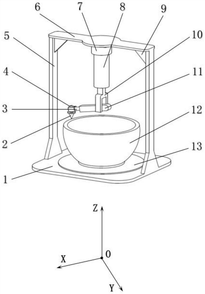
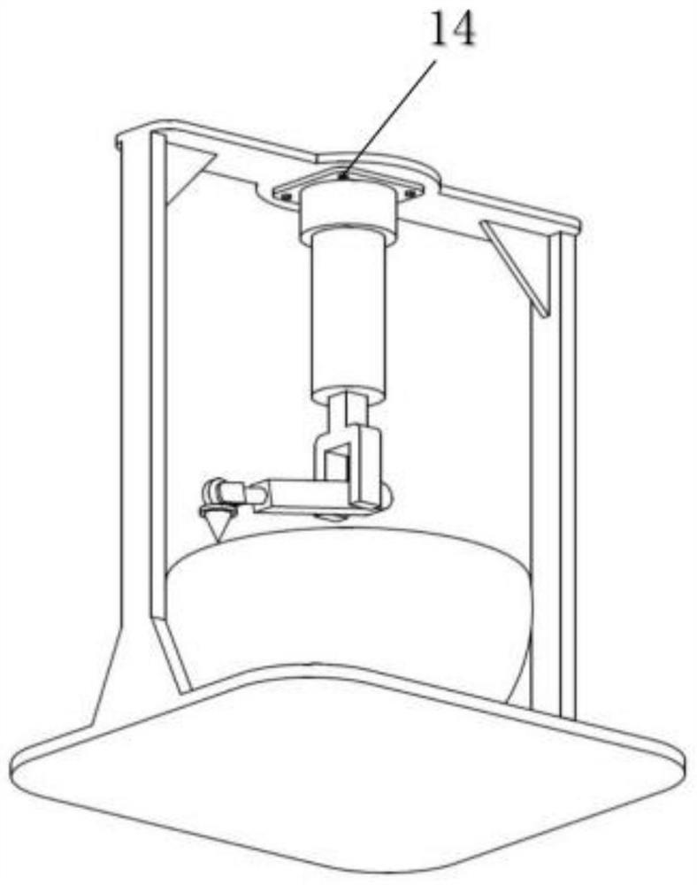
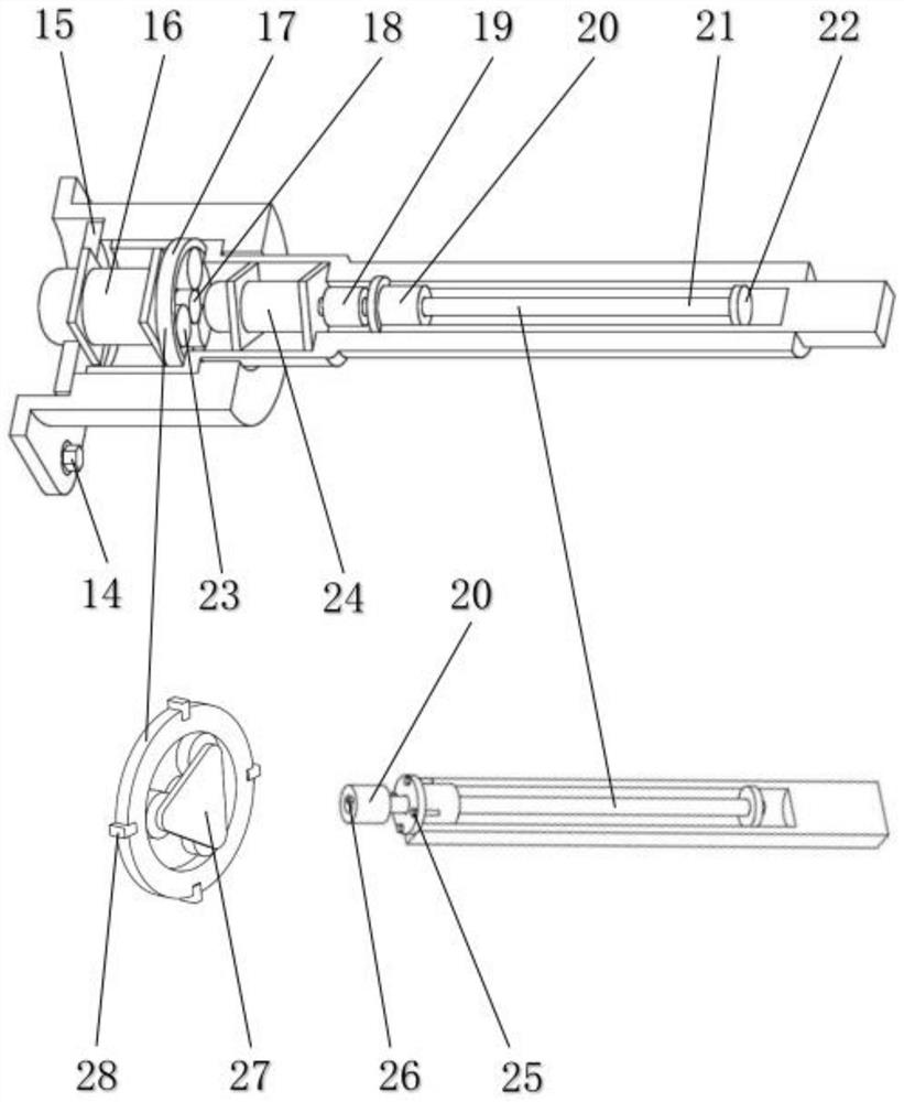
[0020] Attached below Figure 1-3 The technical scheme of the present invention is described in further detail with the specific embodiment:

[0021] A 4D printing system based on a spherical coordinate system, including a base 1, a vertical bar 5, a horizontal plate 6, a rib 9, a printed part 12, a workbench 13, and a nozzle 2. The base 1 supports each of the 4D printing systems. The components also include nozzle steering mechanism, horizontal driving mechanism, cross-bar steering mechanism and vertical driving mechanism; one end of the nozzle steering mechanism is connected to one end of the horizontal driving mechanism, and the horizontal driving mechanism and the vertical driving mechanism are connected by a cross-bar steering mechanism. connection, the vertical drive mechanism is installed on the horizontal plate 6; the nozzle steering mechanism is used to change the orientation of the nozzle 2, so that the angle between the nozzle 2 and the surface of the printed part 1...


PUM


Abstract

A 4D printing system based on a spherical coordinate system, including a base, a vertical bar, a horizontal plate, a rib plate, a printed part, a workbench, a nozzle, and a nozzle steering mechanism, a horizontal driving mechanism, a horizontal bar steering mechanism and a vertical Driving mechanism; the nozzle steering mechanism is used to change the direction of the nozzle, the horizontal driving mechanism is used to control the lateral size of the nozzle along the diameter of the worktable and the printed piece, and the crossbar steering mechanism is used to adjust the horizontal driving mechanism and vertical driving The included angle between the mechanisms adjusts the height between the nozzle and the workbench, and the vertical drive mechanism is used to make the horizontal drive mechanism move up and down in the vertical direction and rotate around the vertical direction. The invention can keep the nozzle perpendicular to the surface of the printed object, keep the distance between the lines formed by the nozzle ejected material in the layer-by-layer printing of the printer, and keep the solidification degree between the printed materials inside the printed object. Uniform and consistent, improving printing strength and precision.

Description

technical field [0001] The invention belongs to the technical field of 3D printing, and in particular relates to a 4D printing system based on a spherical coordinate system. Background technique [0002] At present, the working structure of traditional 3D printers is mostly an orthogonal structure in three-dimensional space, and the method of flat layered printing is often used to realize the processing and molding of the entire printed part. The movement in the three directions of the axis and the Z axis is a mobile pair connected in series. Therefore, during the printing process of the printed part of the traditional 3D printer, the movement error of the nozzle relative to the three coordinate axes is directly accumulated. That is, the total position error of the nozzle relative to the origin of the coordinate system will be greater than the error in a single direction, which directly affects the printing accuracy and surface roughness of the printed part. [0003] At the...

Claims


Application Information

Patent Timeline
Patent Type & Authority Patents(China)
IPC IPC(8): B29C64/112B29C64/20B29C64/227B33Y10/00B33Y30/00
CPCB33Y10/00B33Y30/00B29C64/112B29C64/20B29C64/227
Inventor 王庚祥韦凯鹤
Owner 西安维度智能科技有限责任公司
Learn More