
Memristor circuit

A memristor and circuit technology, applied in the field of circuit design, can solve the problems of difficulty in accurately simulating the voltage and current characteristics of the memristor, large errors in circuit data, and complex principles, and achieves changes in volt-ampere characteristics, simple structure, and realization of thresholds. effect of change

Active Publication Date: 2019-09-03
HANGZHOU DIANZI UNIV
View PDF8 Cites 1 Cited by
  • Summary
  • Abstract
  • Description
  • Claims
  • Application Information

AI Technical Summary

Problems solved by technology

Few memristor equivalent circuits composed of hardware circuits are difficult to apply to actual circuits because of their complex principles; or because of large circuit data errors, it is difficult to accurately simulate the actual memristor voltage, Current characteristics

Method used


Image

  • Memristor circuit
  • Memristor circuit
  • Memristor circuit

Examples


Embodiment Construction

[0017] The examples of the present invention will be described in detail below in conjunction with the accompanying drawings.

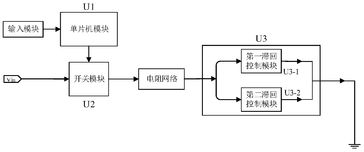
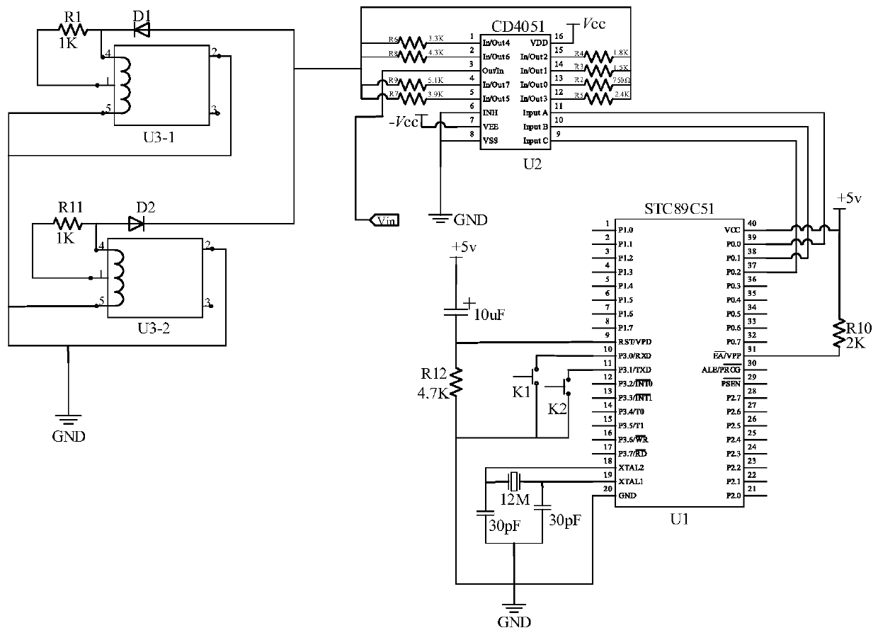
[0018] Depend on figure 1 As shown, the functional block diagram of the memristor circuit of the present invention includes an input module, a single-chip microcomputer module U1, a resistor network, a switch module U2 and a hysteresis control module U3. The first hysteresis control module U3-1 and the second hysteresis control module U3-2 in the hysteresis control module U3 cooperate with the load resistance in the resistor network to form a bidirectional hysteresis unit with switching characteristics. The single-chip microcomputer module U1 inputs signals to the single-chip microcomputer through the buttons in the input module, and then acts on the switch chip to adjust the load resistance in the resistor network. The above four modules are common components in the laboratory, which are relatively easy to realize on the hardware circuit, and can re...


PUM


Abstract

A memristor circuit comprises an input module, a single chip microcomputer module U1, a switch module U2, a resistance network and a hysteresis control module U3, wherein the input module is connectedwith the single chip microcomputer module U1 and is used for configuring the threshold voltage and the resistance value of the memristor; the single-chip microcomputer module U1 is connected with theswitch module U2 and is used for controlling the switch module U2 to control the threshold voltage and the resistance value of the memristor; the switch module U2 is separately connected with the input end Vin, the single-chip microcomputer module U1 and the resistor network and is used for selecting different channels of the resistor network according to the control instruction of the single-chip microcomputer module U1. One end of the resistor network is connected with the switch module U2, and the other end of the resistor network is connected with the hysteresis control module U3 and is used for outputting a resistor with a corresponding resistance value, and the hysteresis control module U3 is connected with the resistance network and the ground and is used for simulating the generation of a bidirectional hysteresis characteristic curve of the memristor.

Description

technical field [0001] The invention belongs to the technical field of circuit design, and relates to a memristor circuit, in particular to a hardware analog circuit for realizing the relationship between voltage and current of the memristor. Background technique [0002] Memristor is a two-terminal passive device used to describe the relationship between magnetic flux and charge. It is a new type of non-linear resistor with memory function. Its resistance is determined by the direction and quantity of charges flowing through it. The amount of electric charge that flows through every moment, thus possessing memory. Due to its ultra-small size, extremely fast erasing speed, ultra-high erasing life, multi-resistive switching characteristics and good CMOS compatibility, memristors are used in non-volatile memories, large-scale integrated circuits, and artificial nerves. Network and artificial intelligence have huge research potential. The advent of memristors has had a huge i...

Claims


Application Information

Patent Timeline
Patent Type & Authority Applications(China)
IPC IPC(8): G11C13/00
CPCG11C13/0021
Inventor 林弥李路平吴巧汪兰叶
Owner HANGZHOU DIANZI UNIV
Learn More