
Electric heating chip structure, mounting method, molding method and wind-driven generator set

A technology of wind turbines and electric heating chips, which is applied in wind engines, wind engines consistent with the wind direction, and wind power generation. It can solve problems such as complex connection methods, large processing depth, and large connection space, and achieve simplified production processes. Reduce the drilling depth and reduce the effect of modification works

Pending Publication Date: 2019-09-03
XINJIANG GOLDWIND SCI & TECH
View PDF14 Cites 2 Cited by
  • Summary
  • Abstract
  • Description
  • Claims
  • Application Information

AI Technical Summary

Problems solved by technology

[0005] However, in this type of electrothermal ice-melting rotor blade, the electrothermal chip and the conductive device are connected by a cylindrical cable to the terminals on both sides of the electrothermal chip. This method of connection requires the use of plastic tubes to connect each bundle of carbon fibers and wires, and then connect the metal wires. Connecting with the bus bar, the connection method is complicated and requires a large connection space. When laying on the blades, a larger modification space is required. When modifying the blades of the running wind turbine, the processing depth of the blades is large. The processing is difficult, and a large amount of work is required to restore the blade surface

Method used


Image

  • Electric heating chip structure, mounting method, molding method and wind-driven generator set
  • Electric heating chip structure, mounting method, molding method and wind-driven generator set
  • Electric heating chip structure, mounting method, molding method and wind-driven generator set

Examples


Embodiment Construction

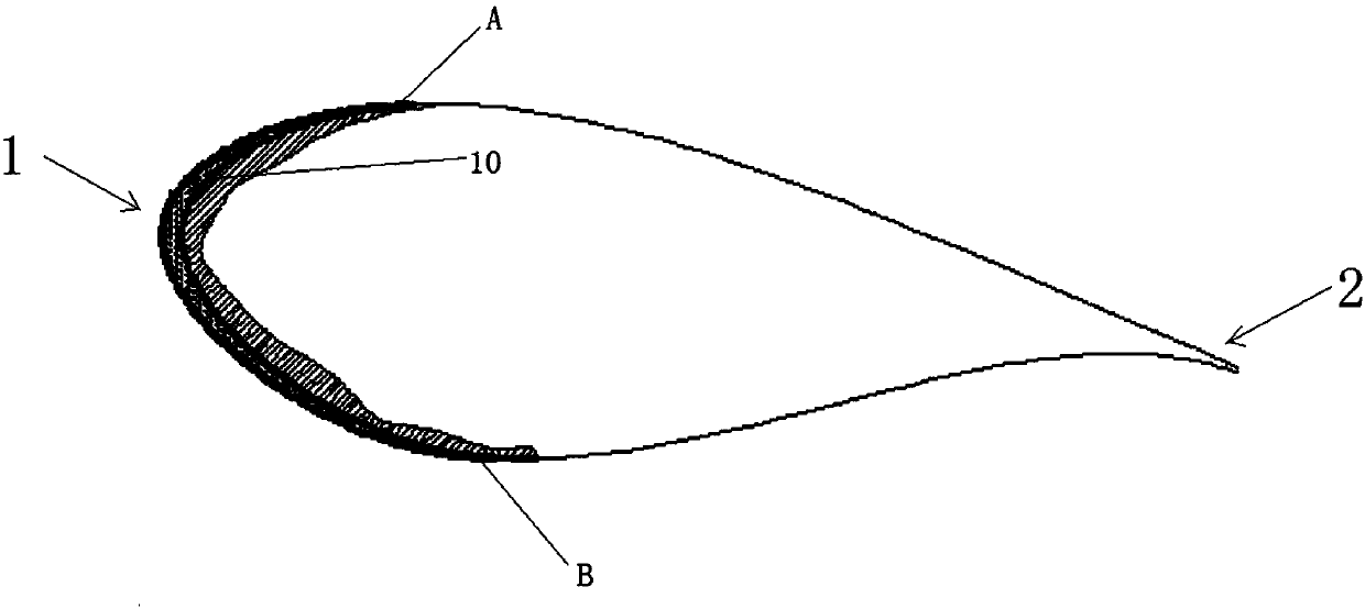
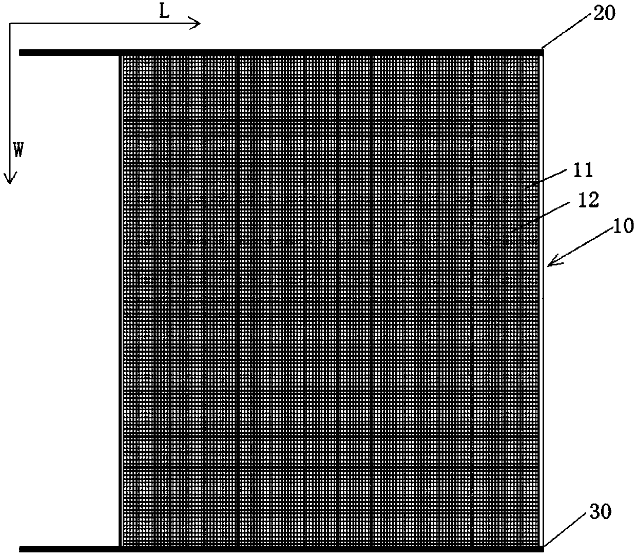
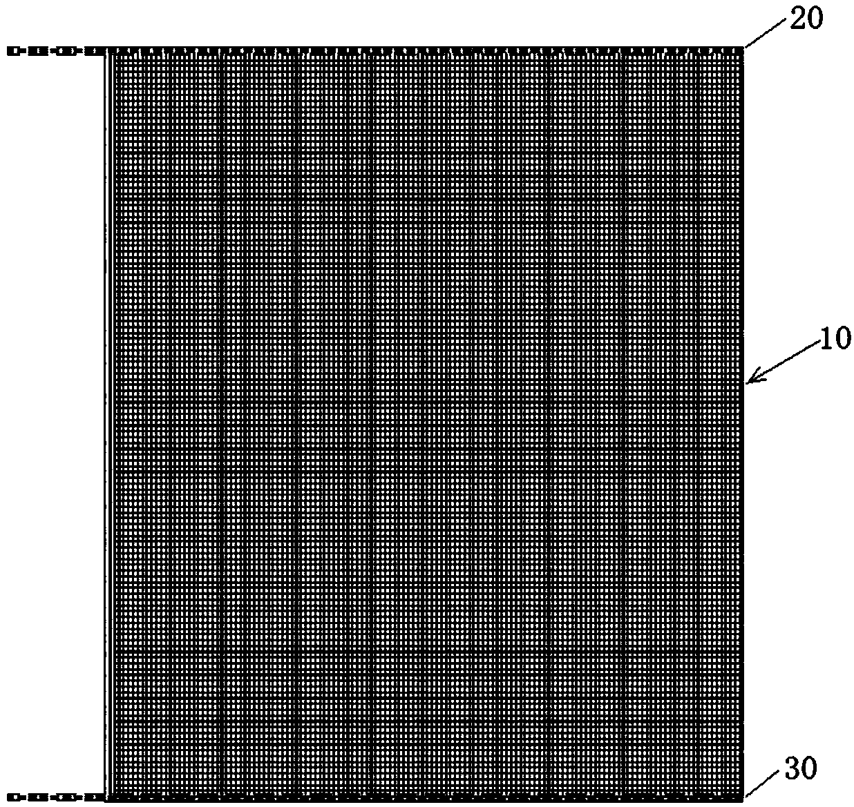
[0028] Hereinafter, embodiments of the present invention will be described in detail with reference to the accompanying drawings, in which the same reference numerals are used to denote the same components.

[0029] According to an exemplary embodiment of the present invention, the electrothermal chip structure for blade ice melting may include an electrothermal chip and a conductive wire, and the electrothermal chip and the conductive wire may be formed into one body and laid in the outer layer of the blade, thereby the blade can be The outer layer is heated to remove the ice layer on the outer surface of the blade, and the electric heating chip and the conductive wire are installed or laid in the outer layer of the blade to facilitate the electrical connection of the electric heating chip and improve the ice-melting efficiency. Combine below image 3 The structure of the electrothermal chip of the present invention is described in detail.

[0030] figure 1 is a schematic d...


PUM


Abstract

The invention discloses an electric heating chip structure, a mounting method, a molding method and a wind-driven generator set. The electric heating chip structure is used for melting ice on a blade,and comprises an electric heating chip; and a positive wire and a negative wire which are integrally formed with the electric heating chip so as to supply power to the electric heating chip, whereinthe integrally formed electric heating, positive wire and negative wire are laid in the outer layer of the blade. The electric heating chip structure can reduce the damage to the outer layer of the blade as much as possible while satisfying a heating demand, and is low in operation complexity. The electric heating chip structure can improve the installation efficiency of an ice melting system, andis simple in electrical connection. The electric heating chip structure simplifies the production process, reduces the modification work of the blade, reduces the processing amount of the blade, reduces the modification difficulty, and shortens the working time.

Description

technical field [0001] The invention relates to the technical field of wind power generation, and more specifically, relates to an electric heating chip structure, an installation method, a molding method and a wind power generator set. Background technique [0002] With the shortage of energy and the enhancement of people's awareness of environmental protection, wind power generation has gradually become the most widely used new energy source. However, due to climate change (for example, freezing rain weather), ice formation will occur on the blades of wind turbines, and the ice on the blades will Layers seriously affect the normal operation of wind turbines. [0003] At present, the following methods are usually used to reduce the impact of the ice layer on the blades: when the blades are frozen to a certain extent, stop the machine for deicing, and wait for the temperature to rise to remove the ice naturally; This reduces the power generation efficiency of the wind turbi...

Claims


Application Information

Patent Timeline
Patent Type & Authority Applications(China)
IPC IPC(8): H05B3/34
CPCH05B3/34F03D80/40F03D80/60H05B2203/017F03D1/0675F05B2230/80Y02E10/72Y02P70/50G05D23/19H05B3/14
Inventor 不公告发明人
Owner XINJIANG GOLDWIND SCI & TECH
Learn More