Alignment structure, robot, contact recognition method, positioning system and medium
An identification method and medical robot technology, applied in the field of positioning system, medium, and alignment structure, can solve the problems of difficult alignment and low alignment accuracy.
- Summary
- Abstract
- Description
- Claims
- Application Information
AI Technical Summary
Problems solved by technology
Method used
Image


Examples
Embodiment 1
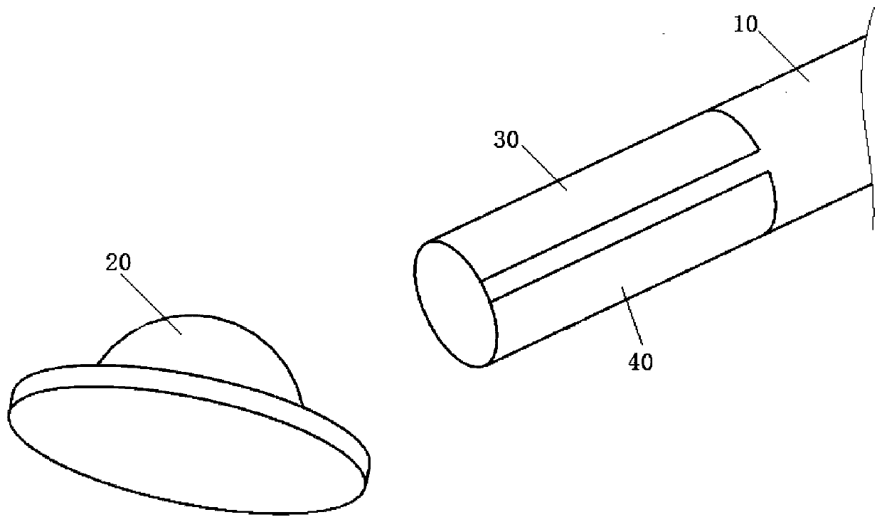
[0028] like figure 1 and figure 2 As shown, this embodiment provides an alignment structure, including a positioning pin 10 and a marking point 20, the marking point 20 has a convex surface, the lower end of the positioning pin 10 is provided with a positioning groove 11, the groove wall of the positioning groove 11 and the marking point The convex surfaces of 20 are all arc surfaces, and the groove walls of the positioning groove 11 can be attached to the convex surfaces of the marking points 20 . When aligning, the positioning groove 11 at the lower end of the positioning pin 10 fits with the raised surface of the marking point 20, and there is surface contact between the two. Compared with the point contact alignment in the prior art, the alignment is easier, and Alignment accuracy is higher.
[0029] Further, the groove wall of the positioning groove 11 and the convex surface of the marking point 20 are both part of a spherical surface, and the curvature of the groove w...
Embodiment 2
[0035] image 3It is a flow chart of a marker point contact recognition method provided by Embodiment 2 of the present invention. The method can be executed by an analysis device, wherein the analysis device can be implemented by hardware and / or software, and is generally integrated in a positioning system. like image 3 As shown, the method includes:
[0036] Step 310, acquiring the voltage of each marking point through the positioning needle.
[0037] Wherein, the positioning pin can be arranged at the end of the mechanical arm of the auxiliary medical robot, and is used to connect the marking point with power and ground when in contact with the marking point, and transmit the voltage on the marking point to the analysis device. It should be noted that the analysis device is a chip with logic operation and analysis functions. For example, the analysis device may be a CPU or a PLC or the like. The positioning pin is electrically connected with the setting pin of the analy...
Embodiment 3
[0052] It should be noted that the embodiment of the present invention also provides an auxiliary medical robot, including the alignment structure as described in the first embodiment, and the auxiliary medical robot adopts the mark point contact recognition method as described in the second embodiment to realize Automatically judge whether the positioning needle is in contact with the marking point, and which marking point it is in contact with.
[0053] Figure 5 It is a structural block diagram of a positioning system provided by Embodiment 3 of the present invention. like Figure 5 As shown, the positioning system includes an analysis device and an auxiliary medical robot ( Figure 5 Only the alignment structure of the assisted medical robot is drawn in ).
PUM
 Abstract
Description
Claims
Application Information
 - R&D
- Intellectual Property
- Life Sciences
- Materials
- Tech Scout
- Unparalleled Data Quality
- Higher Quality Content
- 60% Fewer Hallucinations
Browse by: Latest US Patents, China's latest patents, Technical Efficacy Thesaurus, Application Domain, Technology Topic, Popular Technical Reports.
© 2025 PatSnap. All rights reserved.Legal|Privacy policy|Modern Slavery Act Transparency Statement|Sitemap|About US| Contact US: help@patsnap.com