Circulating condensation boiler

A technology for condensing boilers and boiler shells, which is used in steam boilers, steam boiler accessories, boiler cleaning devices, etc., can solve the problems of reduced boiler safety, low operation efficiency, slow steam production speed, etc. Compact structure and small water level fluctuation

Pending Publication Date: 2019-09-06
江苏科诺锅炉有限公司
View PDF1 Cites 0 Cited by
  • Summary
  • Abstract
  • Description
  • Claims
  • Application Information

AI Technical Summary

Problems solved by technology

[0002] At present, gas-fired boilers are mainly divided into two types: vertical and horizontal. Although the horizontal gas-fired boiler can achieve flue gas condensation and recovery, it has the following disadvantages: large footprint, poor site adaptability; large water volume, large body heat dissipation loss , the actual operation efficiency is low, the steam production speed is slow, the start-up loss is large, the water intake needs thermal deoxygenation, the exhaust gas temperature is high or an independent water circulation system is required, the corrosion of the condenser is serious, the service life cannot be guaranteed, and the self-control level is relatively backward , the current vertical gas boilers have the following shortcomings and deficiencies: high exhaust gas temperature, low thermal efficiency
[0004] The above-mentioned existing technical solutions have the following defects: the time for the existing boiler to generate steam is relatively long, although the time for the boiler to generate steam can be shortened by reducing the circulating water in the boiler, but the safety of the boiler when the circulating water is reduced Sex will decrease

Method used


Image

  • Circulating condensation boiler
  • Circulating condensation boiler
  • Circulating condensation boiler

Examples


Embodiment 1

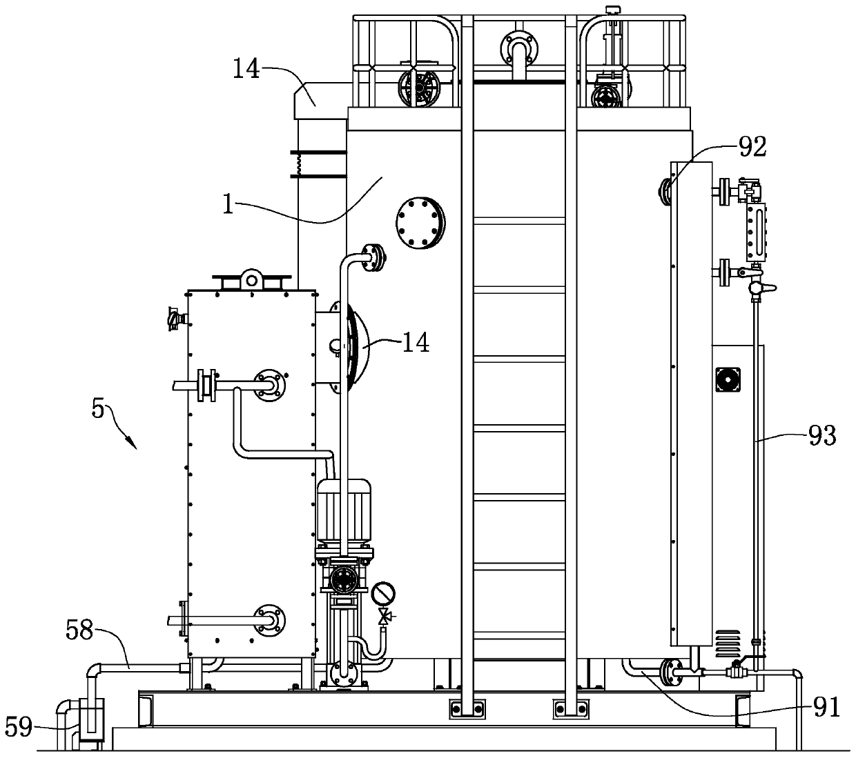
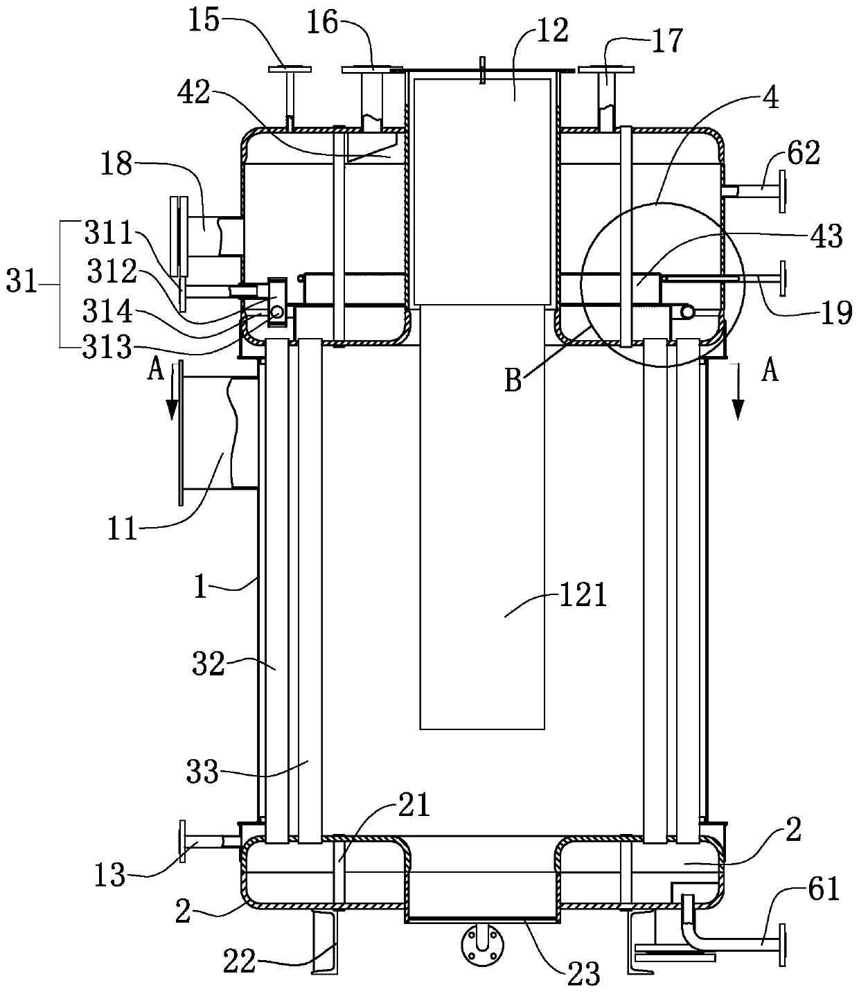
[0039] refer to figure 1 and figure 2 , for the present invention discloses a circulating condensing boiler, comprising a boiler shell 1, the boiler shell 1 is a circular tube shell structure, the inner cavity diameter of the boiler shell 1 is 1230 mm, and the wall thickness of the boiler shell 1 is The axis of the boiler shell 1 is set along the vertical direction. The side of the boiler shell 1 is pierced with a smoke exhaust joint 11 welded to the boiler shell 1 and communicated with the inner cavity of the boiler shell 1. The smoke exhaust joint 11 is located at The part of the boiler shell 1 near the upper end.

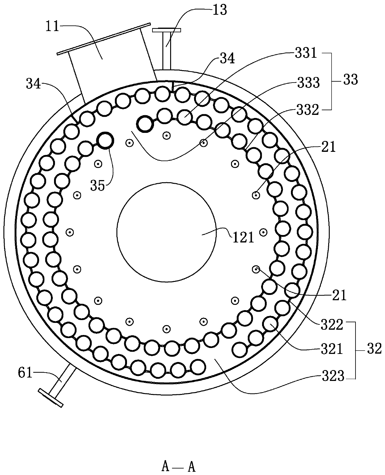
[0040] refer to figure 2 The end of the boiler shell 1 facing the ground is provided with a lower header 2, the lower header 2 is a hollow ring, and the end of the lower header 2 facing away from the boiler shell 1 is fixed on the inner wall of the lower header 2. The disc 23 of the boiler shell 1 is provided with an upper header 4 at one end of the boiler s...


PUM


Abstract

The invention discloses a circulating condensation boiler which comprises a boiler shell. A lower collecting box is arranged at the upper end of the boiler shell; an upper collecting box is arranged at the lower end of the boiler shell; a combustor is arranged on the upper collecting box; a combustion pipe is fixedly arranged at one end, facing the lower collecting box, of the combustor; a disc isfixedly arranged on the inner wall of one end, opposite to the boiler shell, of the lower collecting box; a heat exchange pipe communicating with the lower collecting box and the upper collecting boxis fixedly arranged on the lower collecting box; the heat exchange pipe comprises an outer pipe and an inner pipe, wherein the two ends of the outer pipe respectively communicate with an inner cavityof the lower collecting box and an inner cavity of the upper collecting box, and the inner pipe is positioned on the inner side of the outer pipe; a water inlet device is connected to the inner pipe;an annular partition plate is fixedly arranged at one end, close to the boiler shell, of the inner cavity of the upper collecting box, and the partition plate is located between the circular ring where the outer pipe is located and the circular ring where the inner pipe is located; an upper spacer ring is fixedly arranged at one end, opposite to the boiler shell, of the partition plate; and a steam-water separation device is fixedly arranged on the upper spacer ring, and is arranged above the inner cavity of the upper collecting box; and a steam connector is fixedly arranged on the upper collecting box. The boiler has the effect of quickly producing steam.

Description

technical field [0001] The invention relates to the technical field of boilers, in particular to a circulating condensing boiler. Background technique [0002] At present, gas-fired boilers are mainly divided into two types: vertical and horizontal. Although the horizontal gas-fired boiler can achieve flue gas condensation and recovery, it has the following disadvantages: large footprint, poor site adaptability; large water volume, large body heat dissipation loss , the actual operation efficiency is low, the steam production speed is slow, the start-up loss is large, the water intake needs thermal deoxygenation, the exhaust gas temperature is high or an independent water circulation system is required, the corrosion of the condenser is serious, the service life cannot be guaranteed, and the self-control level is relatively backward , the current vertical gas-fired boilers have the following disadvantages and deficiencies: high exhaust gas temperature and low thermal efficie...

Claims


Application Information

Patent Timeline
Patent Type & Authority Applications(China)
IPC IPC(8): F22B21/06F22B37/22F22B37/26F22B37/44F22B37/54
CPCF22B21/06F22B37/22F22B37/26F22B37/446F22B37/54
Inventor 马凯勤郑大勇
Owner 江苏科诺锅炉有限公司
Why Eureka
Try Eureka