Flux-adjustable magnet vane structure for permanent magnet motor rotor

A permanent magnet motor and magnetic isolation plate technology, applied in the shape/style/structure of the magnetic circuit, the rotating parts of the magnetic circuit, the magnetic circuit, etc. The effect of improved operation, lower cost and improved efficiency

Pending Publication Date: 2019-09-06
苏州英磁新能源科技有限公司
View PDF0 Cites 8 Cited by
  • Summary
  • Abstract
  • Description
  • Claims
  • Application Information

AI Technical Summary

Problems solved by technology

[0004] In view of the above problems, the present invention provides a magnetic isolation plate structure for the rotor of a permanent magnet motor. By arranging magnetic isolation plates at both ends of the rotor iron core, the magnetic flux leakage area of ​​the magnetic steel is controlled by the movement of the slider to ach

Method used


Image

  • Flux-adjustable magnet vane structure for permanent magnet motor rotor
  • Flux-adjustable magnet vane structure for permanent magnet motor rotor
  • Flux-adjustable magnet vane structure for permanent magnet motor rotor

Examples


Embodiment 1

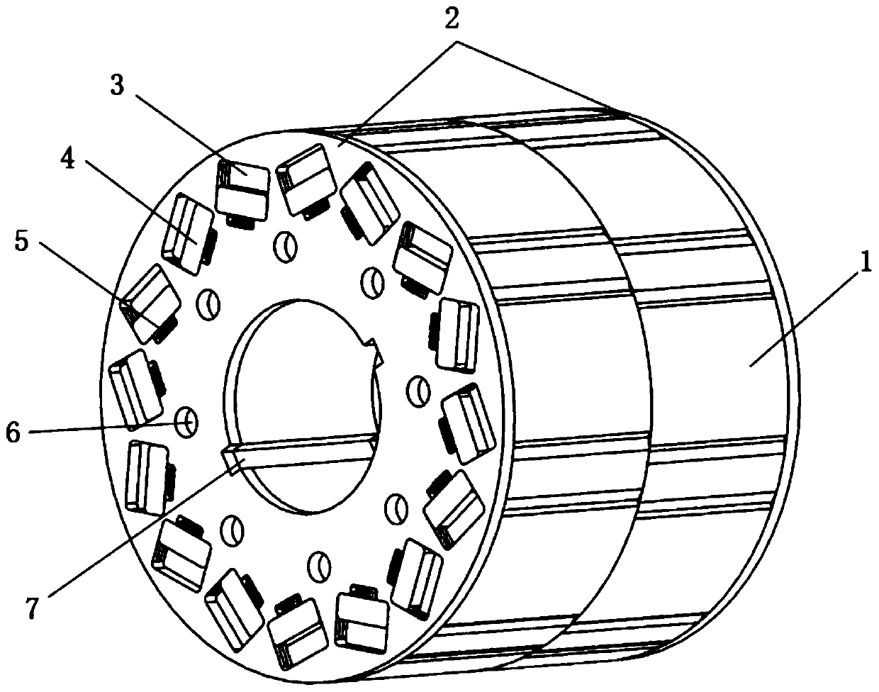
[0037] see figure 1 Among them, 8 sets of V-shaped magnetic steel grooves are embedded on the rotor core, and each V-shaped magnetic steel groove is embedded with a set of magnetic steel. Both ends of the rotor core are respectively equipped with magnetic isolation plates. There are 16 slider holes that correspond to the magnetic steel one by one. Among them, there is an included angle between every two slider holes. This included angle is consistent with the V-shaped included angle of the V-shaped magnetic steel groove. The area of ​​the block hole is larger than the area of ​​the magnetic steel groove, and the length direction of the slider hole is smaller than the length of the magnetic steel to ensure that the magnetic steel will be blocked when the rotor moves and will not be thrown out. The width direction of the slider hole is the magnetic steel. 2-2.5 times the width of the steel to ensure that the slider can effectively cover the area of ​​the magnetic steel when it m...

Embodiment 2

[0048] The rotor iron core is made of laminated rotor punching sheets. There are through holes and key slots on the iron core. The slot holes for placing magnetic steel on the rotor punching sheet form a V-shaped structure in pairs. Correspondingly, the slider holes are also in pairs. A V-shaped layout.

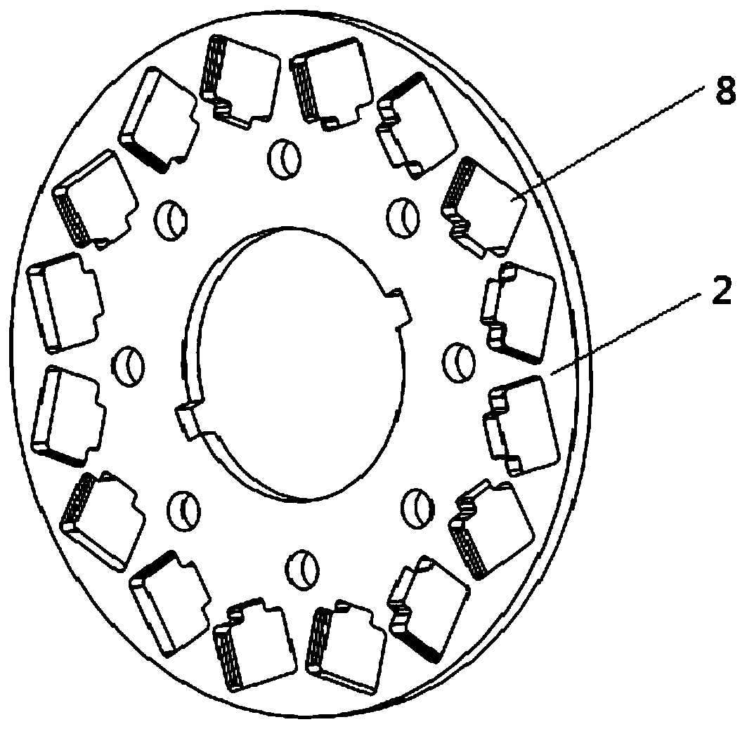
[0049] Furthermore, a mounting hole is provided at the center of the rotor core, and a set of corresponding key grooves 7 is provided on the inner wall of the mounting hole. A group of through holes are distributed around the mounting hole, and the positions of the through holes match the holes of the sliders. A through hole 6 is correspondingly provided at the gap position between the block holes.

[0050] The main body of the slider hole is a square groove for placing the slider. The inner side of the square groove is provided with a hole for placing an elastic member. The width of the hole for placing the elastic member is 1 / 4 of the width of the slider hole, and the lengt...

Embodiment 3

[0061] The rotor iron core is made of laminated rotor punches, with through holes and key slots on the iron core, and the structure of the rotor punches is V-shaped.

[0062] There is a slider hole on the magnetic isolation plate, the hole is parallel to the magnetic steel groove, grooves are provided on both sides of the slider hole, the function is to make the slider slide; the length of the slider hole is slightly smaller than the length of the magnetic steel to prevent the magnetic steel from being thrown out.

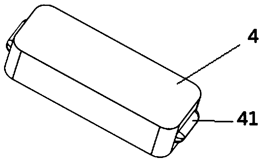
[0063] The slider is made of magnetically conductive material, and there are convex strips 41 on both sides of the slider, which are in the shape of arc strips and fit with the grooves on both sides of the hole of the slider. The slider width is the same as the permanent magnet width.

[0064] The spring connects the slider to the inner wall of the slider hole. In the natural state, the slider is pulled to the bottom of the slider hole. When the motor is running a...


PUM

PropertyMeasurementUnit
Outer diameteraaaaaaaaaa

Abstract

The invention discloses a flux-adjustable magnet vane structure for a permanent magnet motor rotor. A plurality of magnetic steel grooves are embedded into a rotor core; magnetic steel is embedded into the magnetic steel grooves; magnet vanes are arranged at the two ends of the rotor core respectively; a plurality of magnetic conductive sliding block holes which are in one-to-one correspondence with the magnetic steel grooves are distributed on the magnet vanes; slidable sliding blocks are embedded into the sliding block holes; an elastic component used for controlling displacement of each sliding block is arranged on one side of the corresponding sliding block hole; and the effective area of the magnetic steel is controlled through sliding of the sliding blocks. During use, the magnet vanes are arranged at the two ends of the rotor core, the flux leakage area of the magnetic steel is controlled by the movement of the sliding blocks, an function of automatic adjustment of the rotor flux along with the motor operation rotating speed is achieved, and the problems of high counter electromotive force, difficulty in weak magnetism, low operation efficiency and large vibration noise of ahigh-speed area in a wide speed regulation range of the motor in the prior art are solved.

Description

technical field [0001] The present invention mainly relates to the technical field of permanent magnet synchronous motors, in particular to a magnetic isolation plate structure for permanent magnet motor rotors, and in particular to a permanent magnet motor capable of automatically adjusting magnetic flux leakage and reducing motor back EMF during high-speed operation of the motor Rotor magnetic isolation plate structure. Background technique [0002] In the prior art, the built-in permanent magnet synchronous motor has the advantages of high efficiency, high torque density, and wide speed regulation range, and is widely used in automobile drive motors. At present, the main speed regulation range of automobile drive motors is 2.5-3 times. For the speed regulation range of 4 times and above, the built-in permanent magnet synchronous motor has a relatively high no-load back EMF, and the performance of the motor in the high-speed area is poor. The motor rotor flux linkage impr...

Claims


Application Information

Patent Timeline
IPC IPC(8): H02K21/02H02K1/27
CPCH02K1/2706H02K21/028H02K2213/03
Inventor 裴瑞琳郑杭兵徐佳伟
Owner 苏州英磁新能源科技有限公司
Why Eureka
Try Eureka