Direct-current boost double-fed switch reluctance generator current conversion system

A switched reluctance and generator technology, which is applied in the direction of controlling generators, controlling generators, and control systems through magnetic field changes. The output voltage rises, realizes the effect of soft switching operation and large voltage rise

Active Publication Date: 2019-09-06
CHINA JILIANG UNIV
View PDF8 Cites 2 Cited by
  • Summary
  • Abstract
  • Description
  • Claims
  • Application Information

AI Technical Summary

Problems solved by technology

[0004] Using the battery as the separately excited power source to excite the switched reluctance generator has obvious advantages, but the disadvantages of the conventional method are also obvious. First, if the battery cannot be charged, it will require a lot of labor costs and reduce reliability. The winding is only the battery voltage, which cannot achieve the enhanced excitation effect that the switched reluctance generator cares about.
[0005] In the operation of the switched reluctance generator system, the excitation stage and the power generation stage are carried out in different times, which often causes large fluctuations in the output end, and it is impossible to directly obtain a relatively stable continuous current, because generally the output end of the power generation stage receives from The energy supply of phase windings, etc., and the excitation stage is often unable to output power, resulting in low power quality at the output side. Even if the multi-phase winding output is used in parallel mode, although the output power quality will be improved, the problem of large periodic pulsation still exists
[0006] In some application fields, such as the field of switched reluctance wind turbine system driven by wind, the instability of wind force will cause the instability of power generation output. Or short-circuit fault on the load side, the voltage drops suddenly, etc. In serious cases, the switched reluctance generator system will have to be shut down, which will cause the load side to be paralyzed. Even if the excitation power supply such as a battery stores a lot of electric energy, it is often unable to come in handy.

Method used


Image

  • Direct-current boost double-fed switch reluctance generator current conversion system

Examples


Embodiment Construction

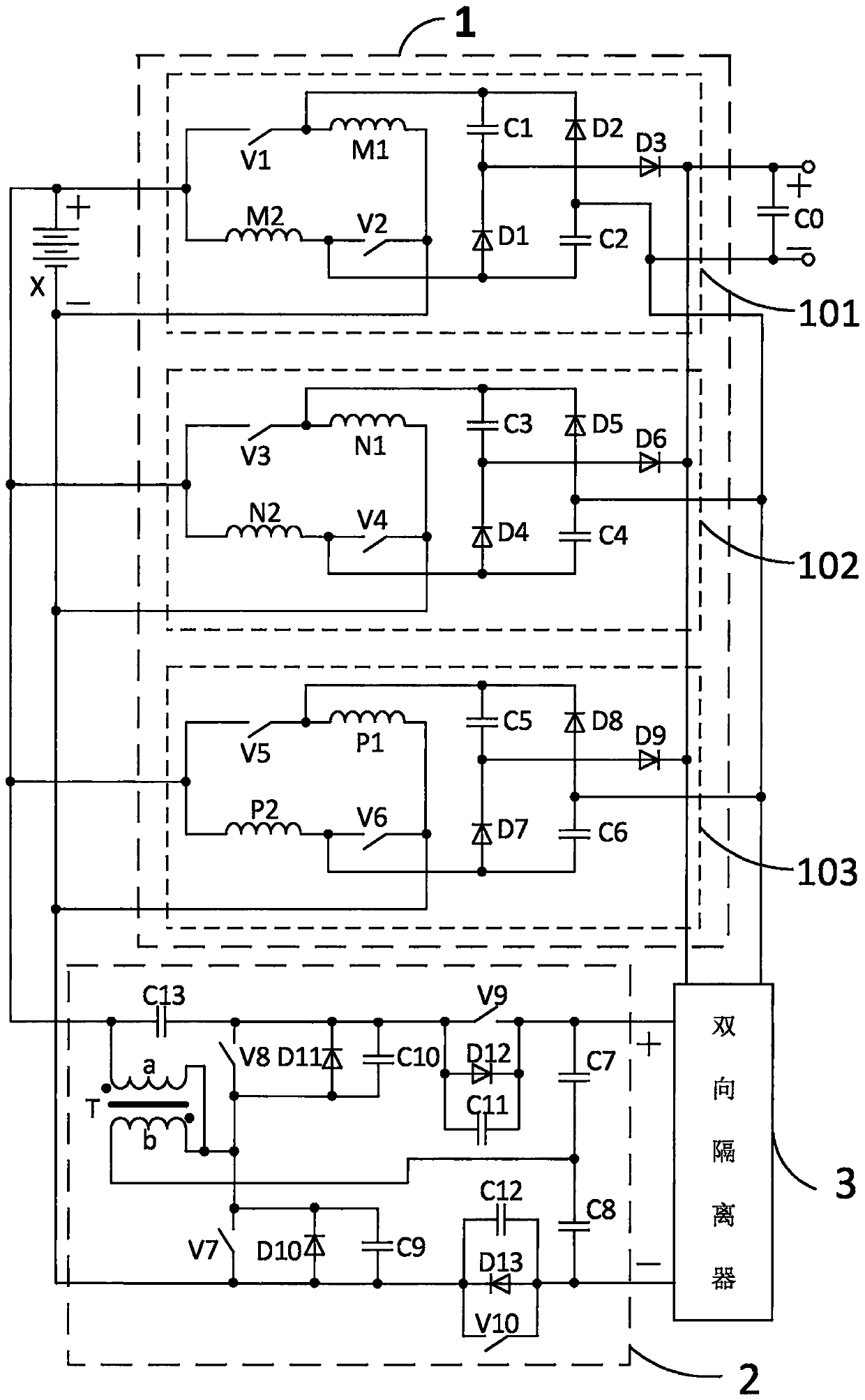
[0036] In this embodiment, a direct-boost double-fed switched reluctance generator converter system, the circuit structure of the converter system is as follows figure 1 As shown, it is composed of battery X, main circuit 1, charging and energy feeding circuit 2, bidirectional isolator 3, and output capacitor C0. Connect the positive and negative terminals of the charging and energy feeding circuit 2 output, the positive and negative terminals of the main circuit 1 output are respectively connected to the positive and negative terminals of the output capacitor C0, and also connected to the two-way isolator 3 input positive and negative terminals, bidirectional isolation The positive and negative ends of the output of the device 3 are respectively connected to the positive and negative ends of the charging and energy feeding circuit 2 input, and the positive and negative ends of the output capacitor are the power generation output power terminals of the switched reluctance gener...


PUM


Abstract

Disclosed is a direct-current boost double-fed switch reluctance generator current conversion system. The direct-current boost double-fed switch reluctance generator current conversion system is composed of a storage battery, a main circuit, a charging and energy feeding circuit, a bidirectional isolator and an output capacitor; the main circuit is composed of phase circuits of respective phase windings, each phase circuit is in parallel connection with each other, the storage battery provides excitation, and each phase circuit can realize the enhancement excitation effect of one time amplification when the excitation voltage is increased during excitation, the voltage of the output side can be obviously higher than that of the storage battery at the input side, and meanwhile, the problemthat continuous output current cannot be obtained at the output side of the excitation stage in the operation of the switched reluctance generator is solved, and the storage battery participates in output in the excitation stage, so that the output side electric energy quality is higher; the charging and energy feeding circuit can automatically charge the storage battery positively, and the electric energy of the storage battery can be reversely output to a load side under the extreme condition, so that the adaptability of the system is improved; and the system is suitable for being applied tomedium-high-speed medium-and-small-sized switched reluctance generator systems under various power drives.

Description

technical field [0001] The invention relates to the field of switched reluctance motor systems, in particular to a switched reluctance generator converter system with direct voltage boosting, continuous output, automatic charging and reverse energy feedback and a control method thereof. Background technique [0002] The switched reluctance motor has a simple and firm structure, strong fault tolerance, no winding on the rotor, and low heat dissipation pressure, so it has broad prospects for application as a generator. [0003] In most generator applications, the general application field of switched reluctance generators is the same. After generating electric energy, it needs to be boosted by a special booster device to meet the needs of the load side. [0004] Using the battery as the separately excited power source to excite the switched reluctance generator has obvious advantages, but the disadvantages of the conventional method are also obvious. First, if the battery cann...

Claims


Application Information

Patent Timeline
Patent Type & Authority Applications(China)
IPC IPC(8): H02P9/30H02P9/38H02P101/15
CPCH02P9/305H02P9/38H02P2101/15
Inventor 孙冠群金尔崇何金龙
Owner CHINA JILIANG UNIV
Why Eureka
Try Eureka