U-shaped wire forming machine

A forming machine and U-shaped technology, applied in the field of U-shaped line forming machines, can solve problems such as unstable quality, increased labor intensity, and low efficiency, and achieve the effects of reducing the risk of work-related injuries, reducing workload, and improving efficiency

Inactive Publication Date: 2019-09-10
徐州奔蓝机械科技有限公司
View PDF0 Cites 1 Cited by
  • Summary
  • Abstract
  • Description
  • Claims
  • Application Information

AI Technical Summary

Problems solved by technology

U-shaped wires made of metal materials are common structural hardware wires in daily life. Its structure is formed by rolling and bending a wire rod with a symmetrical structure. Because of its good elastic support and saving structural materials, it is mainly used to cooperate with other structures. The object is loaded and used under stress. It is light and flexible to use. It has good air permeability and stable structure. It is widely recognized. Fix the middle part of the wire, and then manually use the rolling bending machine to bend the straight wire on both sides one by one, and then remove the formed U-shaped wire after bending. This traditional processing method requires manual participation in picking and placing the workpiece. In addition, manual bending is required to form a symmetrical structure on both sides. The quality of manual processing is unstable and the molding effect is not good, and because workers need to repeat processing actions, it will increase labor intensity and take up more man-hours, resulting in low efficiency. Therefore, it is necessary to propose A new technical solution to solve the above problems

Method used


Image

  • U-shaped wire forming machine
  • U-shaped wire forming machine
  • U-shaped wire forming machine

Examples


Embodiment Construction

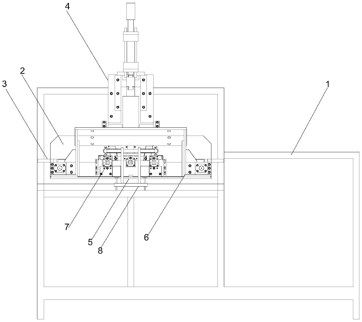
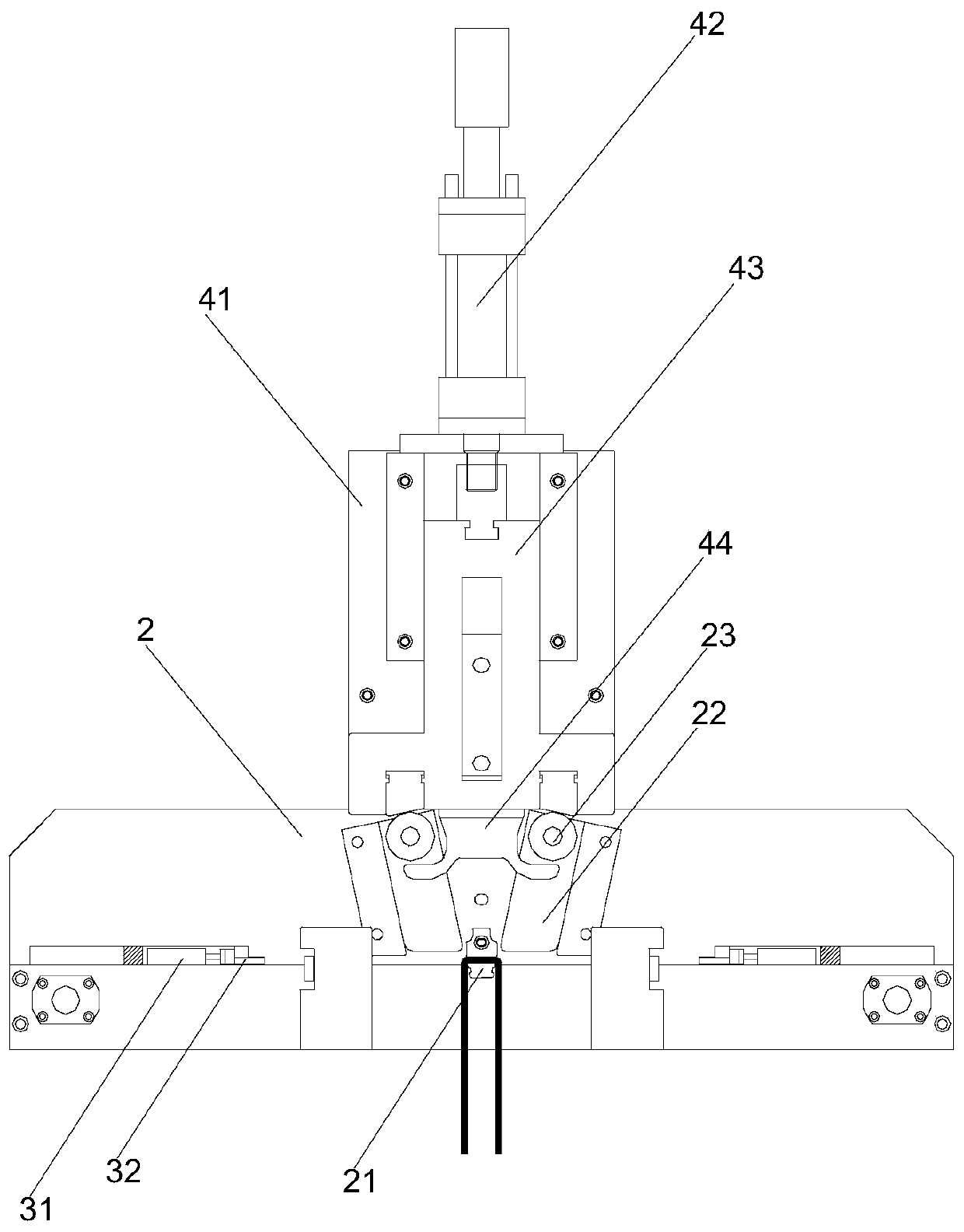
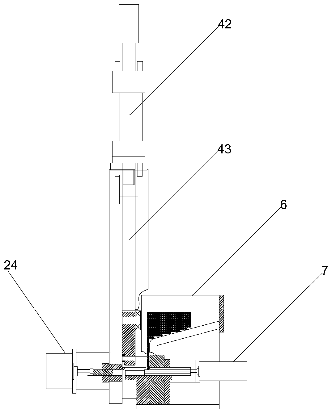
[0021] Such as Figure 1-Figure 3 As shown, the U-shaped wire forming machine of the present invention includes a frame 1, a processing plate 2 vertically fixed on the frame beam on the frame 1, and a knuckle is provided in the middle of the front of the processing plate 2 The mold core 21, the two sides of the corner mold core 21 are provided with a structurally symmetrical support device 3 on the surface of the processing plate 2, and the top of the processing plate 2 is provided with a wire bending device 4 for cooperating with the wire rolling on the angle mold core, The bending device 4 includes a bending vertical plate 41 fixed on the top of the processing plate 2. The bending vertical plate 41 is equipped with a bending oil cylinder 42 whose action direction is perpendicular to the corner die core 21. The movable end of the bending oil cylinder 42 is connected to There is a bending slider 43, and the lower part of the bending slider 43 is located on the front of the pro...


PUM


Abstract

The invention belongs to the technical field of wire machining equipment, and particularly relates to a U-shaped wire forming machine. The U-shaped wire forming machine comprises a machine frame whichis provided with a machining plate perpendicularly fixed to a machine frame transverse beam; the middle of the front surface of the machining plate is provided with a beveling mold core; material supporting devices symmetrical in structure are arranged in the positions, on the two sides of the beveling mold core, of the surface of the machining plate; the top of the machining plate is provided with a wire bending device which is used for cooperating with the beveling mold core to complete wire rolling; and the front surface of the machining plate is provided with a feeding assembly used for feeding wires to the beveling mold core and the material supporting device. According to the U-shaped wire forming machine, by arranging the feeding assembly and a discharging assembly which cooperatewith the machine for production on the machine frame, the occupational injury risk in the production process can be reduced while the work loads of workers are decreased, and operation convenience andsafety are ensured; and the U-shaped wire forming machine is reasonable in structure, batch production is facilitated through automatic procedures, the forming quality is high, the U-shaped wire machining technology is improved advantageously, and remarkable economic benefits are brought.

Description

technical field [0001] The invention belongs to the technical field of wire rod processing equipment, in particular to a U-shaped wire forming machine. Background technique [0002] With the continuous development of industrial automation in today's society, automated production lines play an important role in the industry, and the requirements for automation in mass production are extremely high. U-shaped wires made of metal materials are common structural hardware wires in daily life. Its structure is formed by rolling and bending a wire rod with a symmetrical structure. Because of its good elastic support and saving structural materials, it is mainly used to cooperate with other structures. The object is loaded and used under stress. It is light and flexible to use. It has good air permeability and stable structure. It is widely recognized. Fix the middle part of the wire, and then manually use the rolling bending machine to bend the straight wire on both sides one by on...

Claims


Application Information

Patent Timeline
Patent Type & Authority Applications(China)
IPC IPC(8): B21F1/00
CPCB21F1/00
Inventor 陈良旺
Owner 徐州奔蓝机械科技有限公司
Why Eureka
Try Eureka