Welding thermal cycle curve test device and application method thereof

A welding heat cycle and testing device technology, applied in the direction of measuring devices, welding equipment, welding accessories, etc., can solve the problem that the imaging speed cannot meet the temperature change rate of the welding heat cycle, the joint between the thermocouple and the test board cannot be observed, and the measurement of the test area The position is difficult to control and other problems, to achieve the effect of ensuring authenticity, accuracy, and simple structure

Pending Publication Date: 2019-09-10
SHAANXI SCI TECH UNIV
View PDF0 Cites 1 Cited by
  • Summary
  • Abstract
  • Description
  • Claims
  • Application Information

AI Technical Summary

Problems solved by technology

However, the above two methods have their own advantages and disadvantages: the non-contact thermal imaging method can measure the surface temperature at a long distance, the measurement position is flexible, and it can effectively avoid the radiation of the arc light to the human body, but it can only measure the surface temperature of the object, and the measurement equipment Expensive, complex equipment and difficult maintenance, and because the imaging speed cannot meet the temperature change rate of the welding thermal cycle, the test results are often different from the actual welding thermal cycle; and the traditional thermocouple method needs to bury the thermocouple deep in the welding The inside of the test plate needs to be drilled to a certain extent, the operation is heavy, the test equipment is relatively backward, and the joint between the thermocouple and the test plate cannot be observed, and the measurement position of the test area is difficult to control, resulting in a low measurement success rate
To sum up, in the welding thermal cycle curve measurement experiment, the effective contact between the thermocouple and the test plate must be guaranteed throughout the experiment process. In the experiment, the thermocouple usually deviates from the expected position during the welding process, and the final measurement result is The temperature of the nearby air or the air temperature near the test point, causing the experiment to be repeated continuously

Method used


Image

  • Welding thermal cycle curve test device and application method thereof
  • Welding thermal cycle curve test device and application method thereof
  • Welding thermal cycle curve test device and application method thereof

Examples


specific Embodiment

[0053] As a certain specific embodiment of the present invention is as follows:

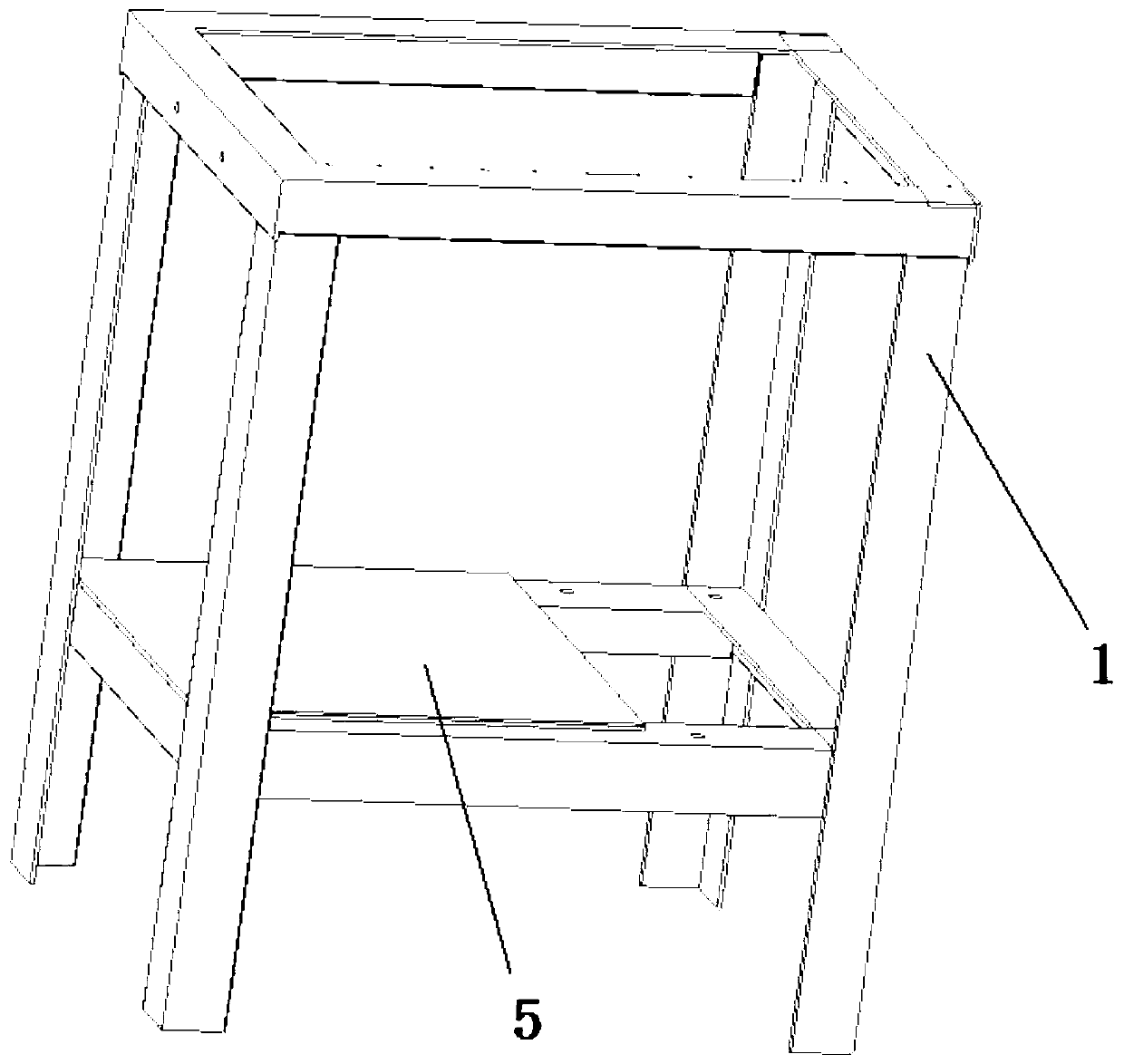
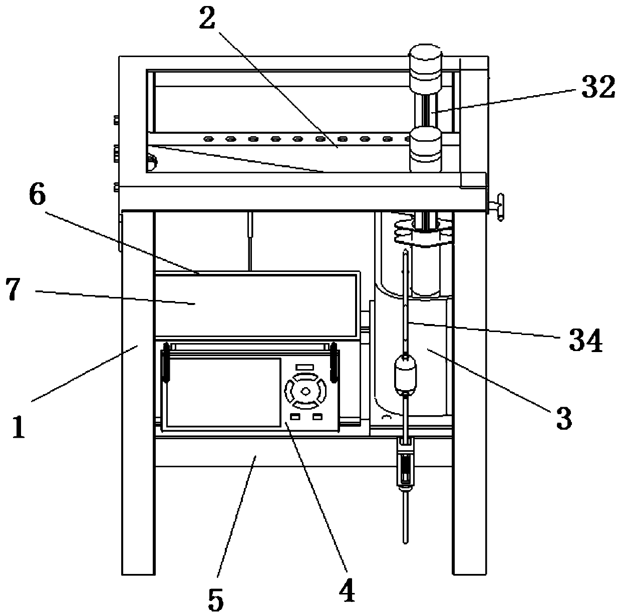
[0054] The support frame 1 is mainly composed of Q235 angle iron, which is connected by means of welding processing. Specifically, it is a frame structure with a height of 402mm, a width of 232mm, and a length of 330mm. The four threaded holes on the side are used to connect the clamping device 2 to the support frame 1. The mounting plate 5 is mainly used as the support of the test system, and the threaded holes on the mounting plate 5 are mainly used to fix the components, and the connecting bolts adopt four standard bolts and nuts of M5×20. The required bolts and nuts are very easy to get at hardware parts stores or Taobao, and the price is cheap.

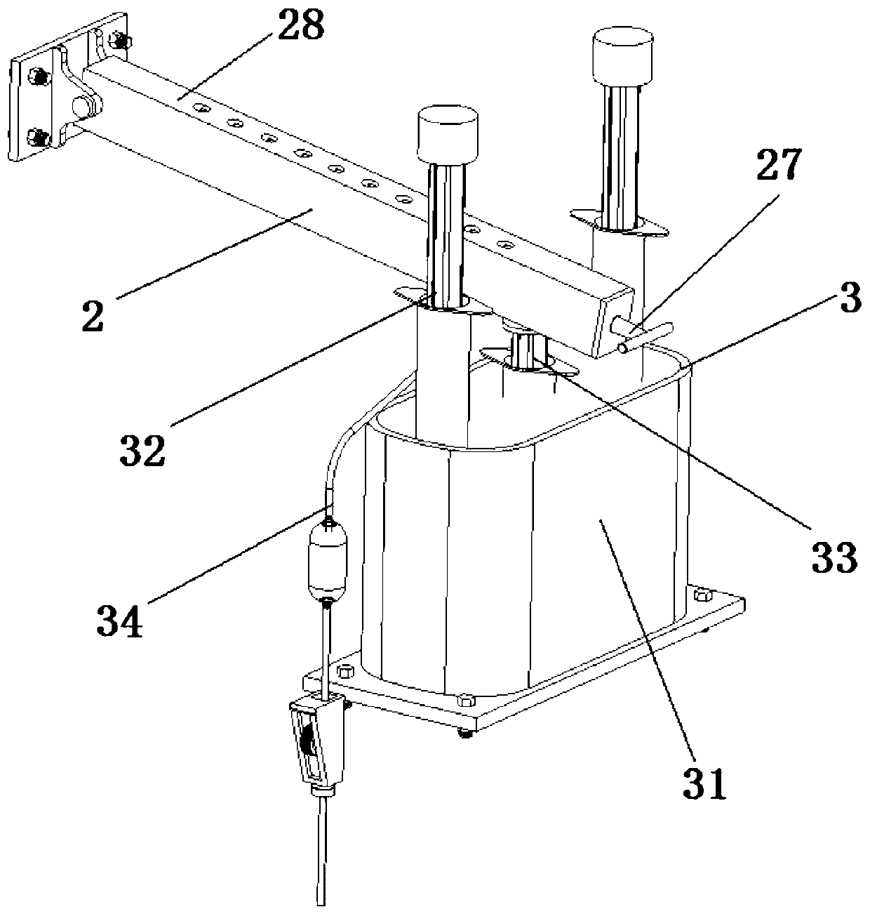
[0055] The clamping device 2 of this embodiment is used to clamp the thermocouple sleeve with a diameter of 4mm. From the perspective of practicability, 10 baffle plates with cylindrical surfaces are designed in the first clamp shell 21 and the seco...


PUM


Abstract

The invention discloses a welding thermal cycle curve test device and an application method thereof. The welding thermal cycle curve test device is characterized in that a workpiece to be tested is placed at the upper opening of a support frame; a thermocouple is clamped on a clamping device; a driving device is used for driving a tightening device to move towards the upper opening of the supportframe, so that the measuring end of the thermocouple is pressed against the workpiece to be tested; and the driving device can be used for tightly pressing the measuring end of the thermocouple against a position to be tested of the workpiece to be tested, so that the thermocouple is prevented from deviating from a desired position in the welding process; the temperature measuring point is real and reliable; operation is easy and convenient; the thermocouple and a test board have good contact performance; and the test accuracy is improved. Through adoption of the device, radiation of arc lightto the human body is avoided. Moreover, the welding thermal cycle curve test device has the advantages of simple structure, and convenience in use and maintenance.

Description

technical field [0001] The invention belongs to the field of welding technology, and in particular relates to a welding thermal cycle curve testing device and a using method thereof. Background technique [0002] Welding is a rapid prototyping method for splicing simple parts into complex parts or components through local melting or mutual diffusion at the joints. It is widely used and has penetrated into various production fields. [0003] Welding technology is widely used in various production fields because of its simple operation and fast realization of a firm connection between components. The influence of welding thermal cycle on the microstructure and performance of the heat-affected zone is very important. The reliability of the welded component connection is a prerequisite for the safe use of the product. Under the condition of a reasonable component design, the safety and reliability are guaranteed by the welding quality. The welding quality It mainly depends on t...

Claims


Application Information

Patent Timeline
Patent Type & Authority Applications(China)
IPC IPC(8): G01K1/14G01K1/02B23K9/095B23K9/32G01K1/022G01K7/02
CPCG01K1/146G01K1/022B23K9/095B23K9/32
Inventor 张伟
Owner SHAANXI SCI TECH UNIV
Why Eureka
Try Eureka