
A frequency-modulated continuous wave ultrasonic imaging system and detection method

An ultrasonic imaging system, a frequency-modulated continuous wave technology, is applied in the analysis of solids using sonic/ultrasonic/infrasonic waves, material analysis using sonic/ultrasonic/infrasonic waves, and measurement devices, etc. It can achieve the effects of improved imaging resolution, stable output voltage, and high measurement accuracy.

Active Publication Date: 2022-04-15
朱爱华
View PDF7 Cites 0 Cited by
  • Summary
  • Abstract
  • Description
  • Claims
  • Application Information

AI Technical Summary

Problems solved by technology

[0002] In the application of medical imaging and the continuity detection of the material interface, the geometric parameter detection of the continuity distribution of related substances and the interface distribution is very important. The current commonly used detection equipment is generally relatively large, relatively expensive, and the imaging resolution is not high. Traditional Imaging detection methods generally use microwave imaging, ultrasonic imaging, infrared imaging, etc.
[0003] In medical imaging applications, the most popular detection method at present is to use ultrasonic detection technology to image and monitor the target object. Common medical imaging ultrasonic frequency ranges from 1MHz to 15MHz. Traditional ultrasonic waves can be divided into continuous wave and pulse wave according to the transmission mode. In two ways, the distance is calculated by the time difference between the transmitted signal and the reflected echo signal. Among them, the most widely used B-ultrasound imaging is to use the time difference between the transmitted wave and the echo to realize the distance detection. Through a series of signal processing and conversion, it finally reaches For the effect of medical imaging, since the transducer will have a relatively long aftershock, it is difficult to distinguish the transmitted wave signal from the echo signal during this period of time, which will cause the measured target object to be within this range. It is indistinguishable from the transmitted wave, forming a detection blind area. On the other hand, the direct time difference detection method has high requirements for the design of the processor main frequency and time voltage conversion circuit, especially the system structure that uses the counter method to measure the time difference. The clock is more demanding
[0004] Due to the limitation of the ultrasonic wavelength, it is generally difficult for the above-mentioned traditional ultrasonic imaging technology to achieve imaging of target objects with a diameter less than 5mm, especially in medical imaging, which is not suitable for imaging detection of early tumors. In addition, the emission of traditional ultrasonic equipment The power is relatively large, and the system power supply voltage is relatively high, which is incompatible with commonly used low-voltage and low-power systems. At present, there is a lack of technical means and effective methods for system realization of such high-resolution, low-power ultrasound imaging.

Method used


Image

  • A frequency-modulated continuous wave ultrasonic imaging system and detection method
  • A frequency-modulated continuous wave ultrasonic imaging system and detection method
  • A frequency-modulated continuous wave ultrasonic imaging system and detection method

Examples


Embodiment

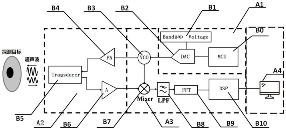
[0038] refer to figure 1 As shown, the present invention discloses an ultrasonic imaging system based on frequency modulation continuous wave, including: frequency modulation continuous wave generation module A1, ultrasonic transmission and echo receiving module A2, signal processing module A3 and display module A4, frequency modulation continuous wave generation module A1 It is electrically connected with the ultrasonic sending and echo receiving module A2, the FM continuous wave generating module A1 is used to generate a frequency signal with a linear relationship between frequency and time in the time domain, and the ultrasonic sending and echo receiving module A2 is used to send FM continuous wave Generate the FM continuous wave generated by module A1 and receive the feedback signal. The output terminal of ultrasonic sending and echo receiving module A2 is electrically connected to the input terminal of signal processing module A3. imaging.

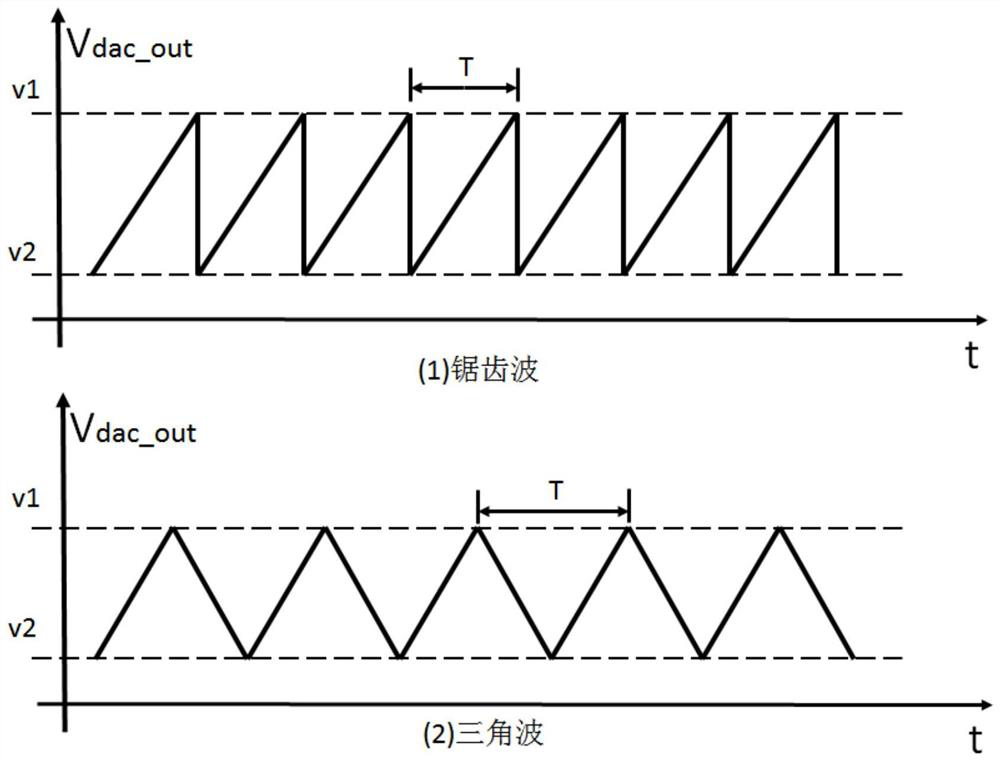
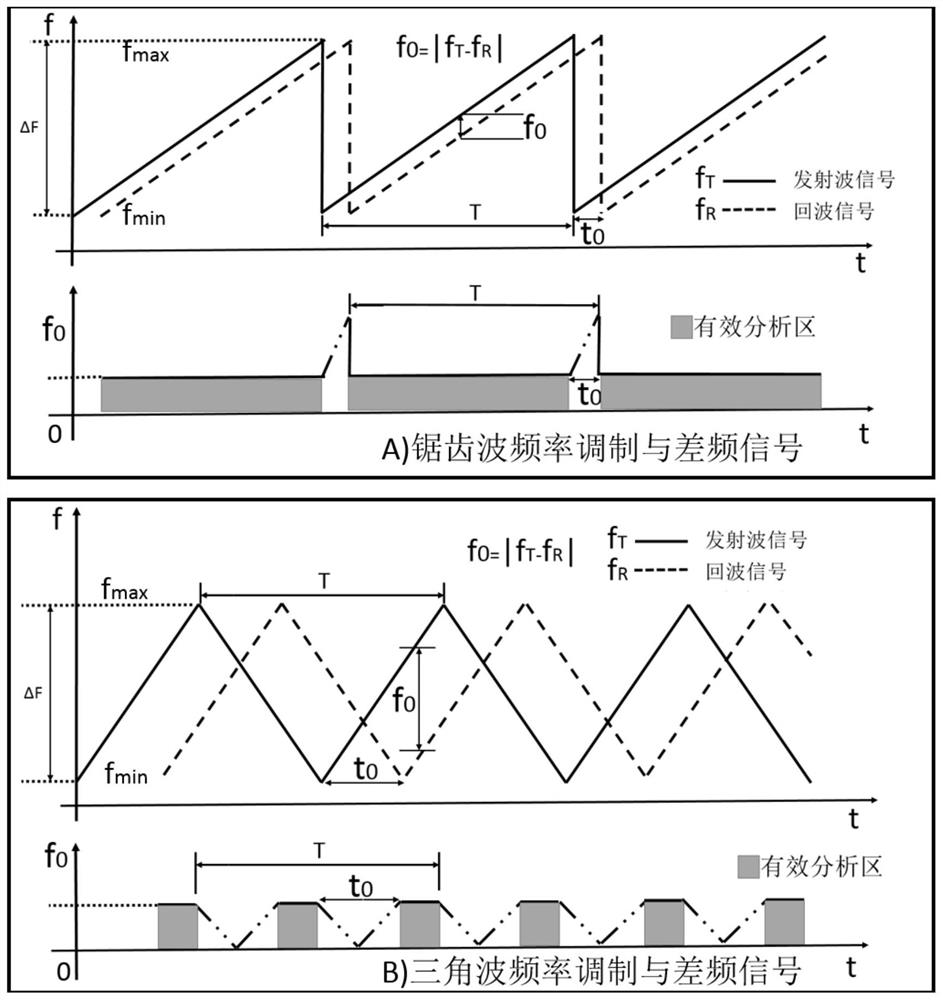
[0039] Cooperate Figure 2-5...


PUM


Abstract

The invention discloses an ultrasonic imaging system and detection method based on frequency modulation continuous wave, which includes a frequency modulation continuous wave generation module, an ultrasonic sending and echo receiving module, a signal processing module and a display module, the frequency modulation continuous wave generation module and the The ultrasonic sending and echo receiving module are electrically connected, the FM continuous wave generating module is used to generate a frequency signal in the time domain with a linear relationship between frequency and time, and the ultrasonic sending and echo receiving module is used to send the FM The frequency-modulated continuous wave generated by the continuous wave generation module receives the feedback signal, the output end of the ultrasonic sending and echo receiving module is electrically connected to the input end of the signal processing module, and the signal processing module processes the received feedback signal The display module performs imaging. The invention has the advantages of no distance blind zone, high resolution and low transmission power, high accuracy in practical process, accurate and effective measurement, simple and practical.

Description

technical field [0001] The invention belongs to the technical field of ultrasonic detection, and in particular relates to an ultrasonic imaging system and detection method based on frequency modulation continuous wave. Background technique [0002] In the application of medical imaging and the continuity detection of the material interface, the geometric parameter detection of the continuity distribution of related substances and the interface distribution is very important. The current commonly used detection equipment is generally relatively large, relatively expensive, and the imaging resolution is not high. Traditional Imaging detection methods generally use microwave imaging, ultrasonic imaging, infrared imaging, etc. [0003] In medical imaging applications, the most popular detection method at present is to use ultrasonic detection technology to image and monitor the target object. Common medical imaging ultrasonic frequency ranges from 1MHz to 15MHz. Traditional ultr...

Claims


Application Information

Patent Timeline
Patent Type & Authority Patents(China)
IPC IPC(8): G01N29/06
CPCG01N29/0654G01N2291/02466
Inventor 胡友德朱爱华
Owner 朱爱华
Learn More