Dynamic reactive power optimal allocation method for power grid based on transient voltage security constraints
A technology of transient voltage and safety constraints, applied in reactive power compensation, circuit devices, AC network voltage adjustment, etc., can solve the problems affecting SVC dynamic reactive power compensation, etc., and achieve the effect of significant control effect
- Summary
- Abstract
- Description
- Claims
- Application Information
AI Technical Summary
Problems solved by technology
Method used
Image


Examples
Embodiment 1
[0065] Such as figure 1 Shown is the flow chart of the grid dynamic reactive power optimization configuration method based on transient voltage safety constraints of the present invention, comprising the following steps:
[0066] S10. Input grid basic data to power system and carry out time-domain transient state simulation, determine the key failure set {F that threatens the transient voltage stability of described power system 1 ,F 2 ,...,F N}, and determine the candidate SVC installation node {1,2,...,m} according to the voltage recovery level of each node during the fault period;
[0067] S20. Install dynamic reactive power compensation device SVC at each node, perform time domain transient simulation again and calculate voltage-reactive power trajectory sensitivity index TSI of node j (j=1,2,...,m) j ;
[0068] S30. according to the calculation result of step S20 to the TSI of each node j Sort and take the largest TSI j The node corresponding to the value is the opt...
Embodiment 2
[0123] This embodiment is an application embodiment of the method in Embodiment 1 in the time-domain transient simulation calculation of the 10-machine 39-node power grid in New England. All loads in the power system are configured with 60% induction motors and 40% constant impedance load ratios. The motor load model parameters adopt the values in Table 1.
[0124] Table 1 Load model parameters of induction motor
[0125]
[0126] The calculation example of this embodiment only examines a specific fault. The time domain transient simulation calculation time of the system is 10s. When t=1s, a three-phase short-circuit fault occurs in the system, and the fault disappears when t=1.1s. The fault point is uniformly set before installing the SVC The node where transient voltage instability occurs in the system.
[0127] The grid topology diagram of the 330kV power grid with 10 machines and 39 nodes in New England is as follows Image 6 As shown, when a three-phase short-circu...
Embodiment 3
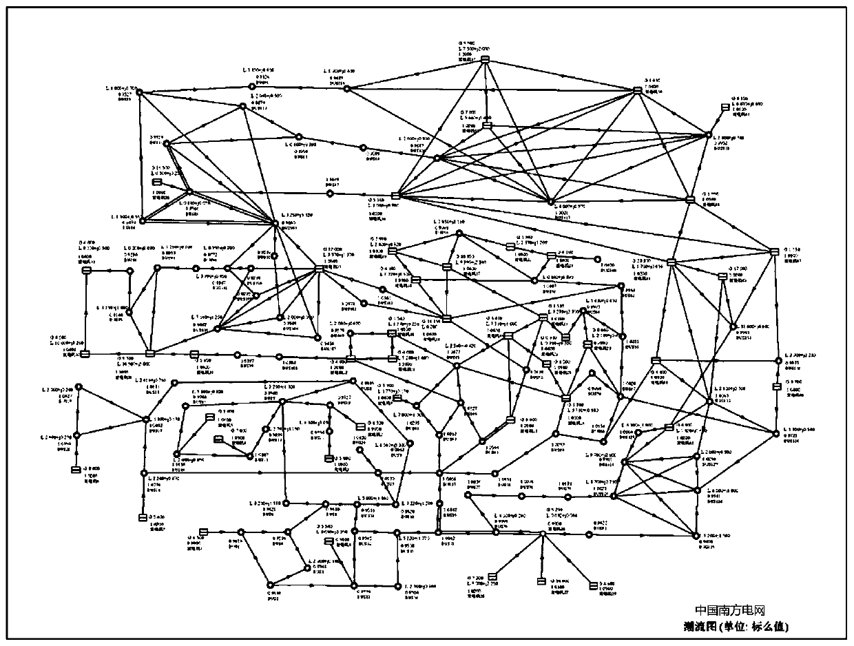
[0129] This embodiment is an application embodiment of the method in Embodiment 1 in the time-domain transient simulation calculation of the large power grid with 47 machines and 140 nodes in Guangdong Power Grid. All loads in the power system are configured with 60% induction motors and 40% constant impedance loads. The parameters of the induction motor load model adopt the values in Table 1. And this embodiment only examines a specific fault, the time domain transient simulation calculation time of the system is 10s, a three-phase short-circuit fault occurs in the system at t=1s, the fault disappears at t=1.1s, and the fault point is uniformly set before the SVC is installed. Node for transient voltage instability.
[0130] The grid structure of 220kV power grid with 47 machines and 140 nodes in Guangdong power grid is as follows Figure 16 shown. For the convenience of description, only one specific fault is still considered, and the fault form is a three-phase short-ci...
PUM
 Abstract
Description
Claims
Application Information