Laser systems utilizing cellular-core optical fibers for beam shaping

A laser system and honeycomb core technology, applied in the field of laser systems, can solve the problems of damage to the optical components of the laser system, time-consuming, expensive, etc.

Active Publication Date: 2019-09-10
PANASONIC OF NORTH AMERICA
View PDF21 Cites 2 Cited by
  • Summary
  • Abstract
  • Description
  • Claims
  • Application Information

AI Technical Summary

Problems solved by technology

In order to change the BPP or beam shape in a conventional laser system, the output optics often have to be swapped out for other components and / or realigned, a process that is time-consuming and expensive, and can even accidentally damage the delicate optics in the laser system

Method used


Image

  • Laser systems utilizing cellular-core optical fibers for beam shaping
  • Laser systems utilizing cellular-core optical fibers for beam shaping
  • Laser systems utilizing cellular-core optical fibers for beam shaping

Examples


Embodiment Construction

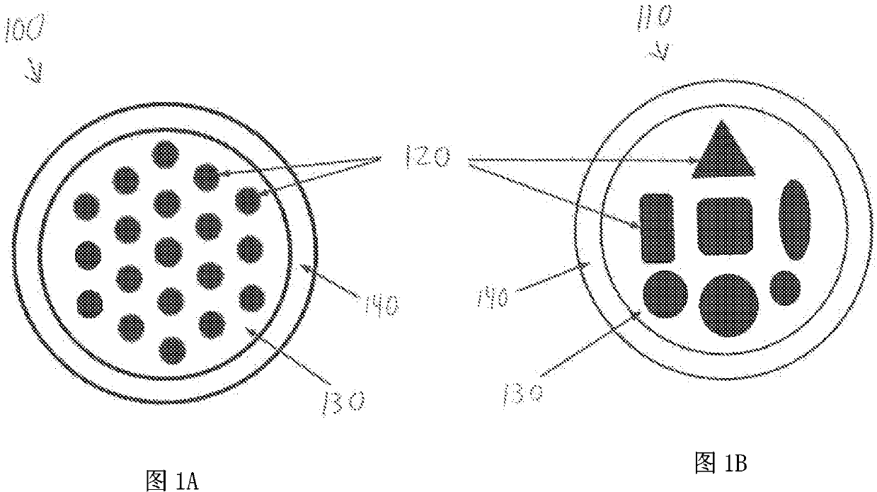
[0043] Figures 1A and 1B Two different exemplary honeycomb core fibers 100, 110 that may be used in various embodiments according to the invention are depicted. As shown, each honeycomb core fiber has a plurality of different core regions 120, each core region having a refractive index (e.g., a refractive index n 0 ). (Although all core regions 120 are described as having the same refractive index in this example, embodiments of the invention include implementations in which one or more core regions 120 have a different refractive index than the other core regions; These indices of refraction are generally greater than those of the intercore cladding region and / or the outer cladding.) While honeycomb core fibers 100, 110 are depicted with various shapes and numbers of core regions 120 (e.g., for fiber 100, its transverse The cross-section is substantially circular; for fibers 110, which have different shapes (e.g., square, rectangular, triangular, oval, circular, etc.)), th...


PUM


Abstract

In various embodiments, the beam parameter product and/or beam shape of a laser beam is adjusted by directing the laser beam across a path along the input end of a cellular-core optical fiber. The beam emitted at the output end of the cellular-core optical fiber may be utilized to process a workpiece.

Description

[0001] related application [0002] This application claims the benefit of priority to U.S. Provisional Application No. 62 / 450,793, filed January 26, 2017, the entire contents of which are incorporated herein by reference. technical field [0003] In various embodiments, the present invention relates to laser systems, particularly laser systems having controllable beam profiles (eg, variable beam shapes). Background technique [0004] High power laser systems are used in many different applications such as welding, cutting, drilling and material processing. Such laser systems usually include a laser emitter and an optical system, the laser light emitted from the laser emitter is coupled into an optical fiber (or "fiber" for short), and the optical system focuses the laser light from the optical fiber to the on the workpiece. Wavelength beam combining (WBC) is a technique used to scale the output power and brightness from laser diodes, laser diode bars, diode bar stacks, o...

Claims


Application Information

Patent Timeline
Patent Type & Authority Applications(China)
IPC IPC(8): H01S3/13H01S3/067G02B6/02
CPCG02B6/3512G02B6/3524G02B6/3598G02B6/4296G02B6/02042G02B6/32G02B6/262G02B6/03605G02B6/34
Inventor F·维拉里尔绍塞多周望龙P·泰伊巴提
Owner PANASONIC OF NORTH AMERICA
Why Eureka
Try Eureka