Reflux device for controlling film thickness of multi-gap pole piece and control method thereof

A reflow device and multi-gap technology, which is applied to the device for coating liquid on the surface, electrode manufacturing, electrode collector coating, etc., can solve the problems of uncontrollable thickness of pole pieces, potential safety hazards, low production efficiency, etc.

Pending Publication Date: 2019-09-13
HUIZHOU LIWINON NEW ENERGY TECH CO LTD
View PDF0 Cites 2 Cited by
  • Summary
  • Abstract
  • Description
  • Claims
  • Application Information

AI Technical Summary

Problems solved by technology

When coating the gap between the tape and the size, two backflow pressures are formed, which makes the head weights of the two film lengths inconsistent, and the thickness of the p

Method used


Image

  • Reflux device for controlling film thickness of multi-gap pole piece and control method thereof
  • Reflux device for controlling film thickness of multi-gap pole piece and control method thereof
  • Reflux device for controlling film thickness of multi-gap pole piece and control method thereof

Examples


Embodiment 1

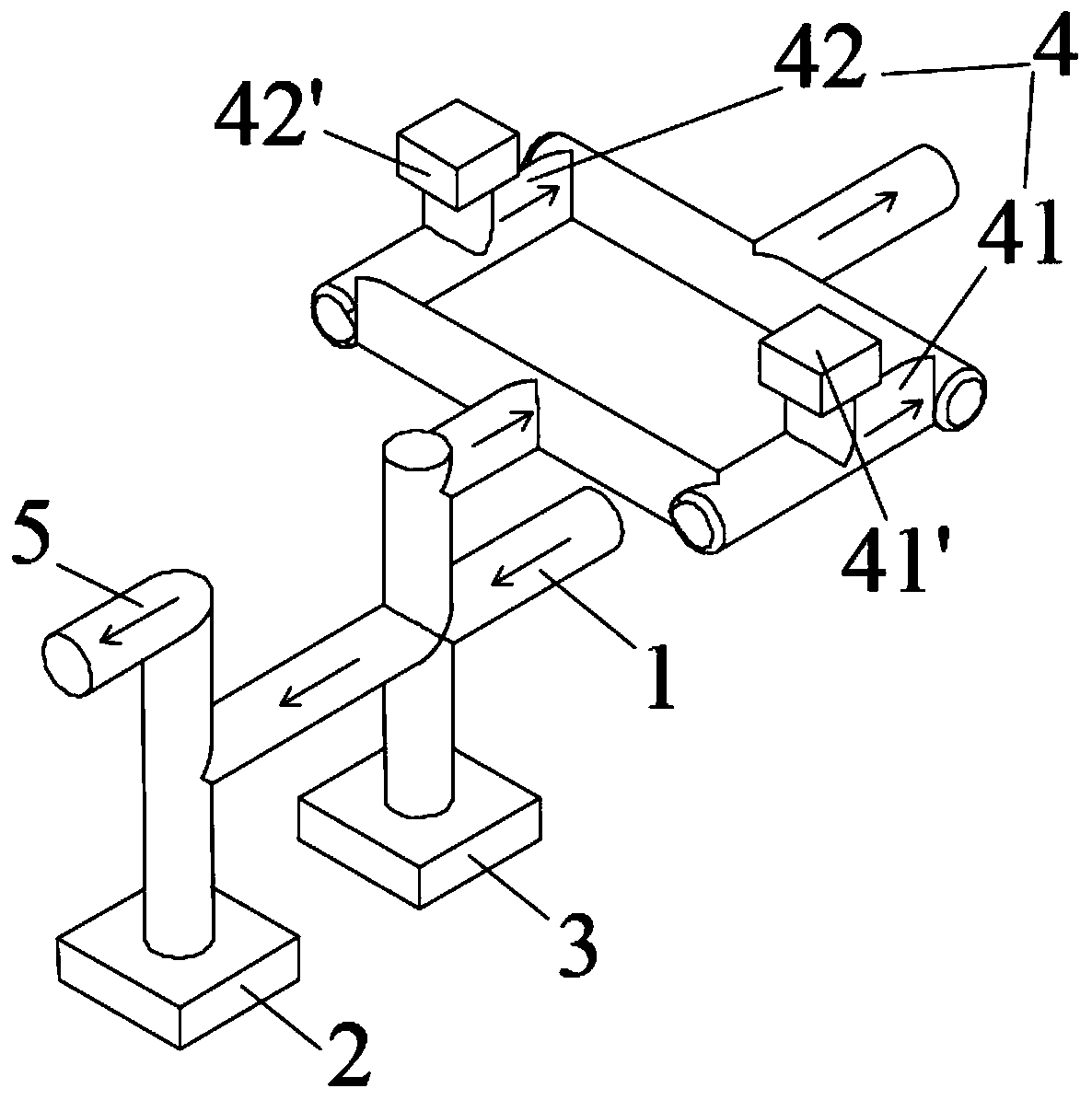
[0037] Such as figure 1As shown, a backflow device for controlling the film thickness of multi-gap pole pieces includes a feed pipe 1, a coating valve 2, a return valve 3, a return pipe 4 and a membrane head pipe 5, and the membrane head pipe 5 communicates with the feed pipe 1 , form the main road, the coating valve 2 and the return valve 3 are sequentially connected in series in the main road, the return pipe 4 communicates with the return valve 3, the return pipe 4 includes a first pipeline 41 and a second pipeline 42, the first pipeline 41 and the second pipeline 42 in parallel. In operation, when coating the membrane area, the screw pump enters the cavity of the membrane head tube 5 to form coating pressure. At this time, the return valve 3 is closed, the coating valve 2 is opened, and the slurry enters the coating membrane head 61 for coating. To the current collector, thereby forming the pole piece; when coating the blank area with large and small gaps, the coating val...

Embodiment 2

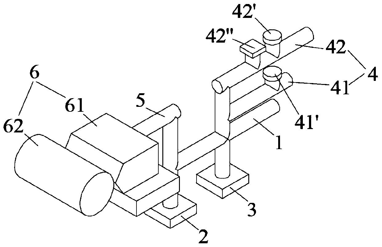
[0047] Such as figure 2 As shown, the difference from Embodiment 1 is that a second manual diaphragm valve 42 ″ is connected in series in the second pipeline 42 in this embodiment. This structural design increases the control mode of the conduction state of the second pipeline 42, which is beneficial to production.

[0048] Preferably, the second manual diaphragm valve 42'' is connected in series between the return valve 3 and the air-operated diaphragm valve 42'. This structural design makes the work of the second manual diaphragm valve 42 ″ unaffected by the air-operated diaphragm valve 42 ′, thereby increasing the stability of the work.

[0049] Other structures are the same as those in Embodiment 1, and will not be repeated here.

Embodiment 3

[0051] Such as Figure 1-2 As shown, a method for controlling the reflow device of Embodiment 1 or 2 to control the film thickness of the multi-gap pole piece includes the following steps:

[0052] Coating diaphragm area, the screw pump enters the cavity of the membrane head tube 5 to form the coating pressure, at this time the return valve 3 is closed, the coating valve 2 is opened, the slurry enters the coating membrane head 61 and is applied to the current collector, forming Pole piece;

[0053] When coating the blank area with large and small gaps, the coating valve 2 is closed, and the slurry backflow adopts the first pipeline 41 and the second pipeline 42 dual-path return slurry to return to the buffer irrigation, and the dual-path return device controls the large and small gap slurry reflow;

[0054] When coating a small gap, the first manual diaphragm valve 41' in the first pipeline 41 is opened, the air-operated diaphragm valve 42' in the second pipeline 42 is close...


PUM


Abstract

The invention belongs to the technical field of batteries, and particularly relates to a reflux device for controlling the film thickness of a multi-gap pole piece. The reflux device comprises a feedpipe, a coating valve, a return valve, a return pipe and a membrane head pipe, the membrane head pipe is in communication with the feeding pipe to form a main trunk line, the coating valve and the return valve are sequentially connected to the main trunk line in series, the return pipe is in communication with the return valve, the return pipe comprises a first pipeline and a second pipeline, andthe first pipeline and the second pipeline are connected in parallel. The reflux device is simple in structure, achieves multi-gap pole piece production, and is simple to operate, stable in work and high in production efficiency. In addition, the invention further provides a control method of the reflux device so as to improve the working stability and efficiency of the reflux device.

Description

technical field [0001] The invention belongs to the technical field of batteries, and in particular relates to a reflow device and a control method for controlling the film thickness of multi-gap pole pieces. Background technique [0002] In the mobile phone battery production process, the coating process evenly coats the slurry on the current collector. The backflow valve in the diaphragm area is closed, the slurry is applied to the current collector through the membrane head, the screw pump enters the cavity of the membrane head to form a coating pressure, the coating valve in the gap area is closed, the slurry returns to the supply tank through the backflow device, and the coating is completed. The backflow pressure is formed in the pipeline cavity of the cloth valve to the backflow diaphragm valve. The reflux device is to control the size of the slurry reflux to control the size of the reflux pressure, thereby affecting the head surface weight (called surface density) o...

Claims


Application Information

Patent Timeline
IPC IPC(8): B05C11/10B05C1/08H01M4/04
CPCB05C1/0826B05C11/1002H01M4/0404Y02E60/10
Inventor 洪远铭王润发纪荣进郑明清李载波杨山
Owner HUIZHOU LIWINON NEW ENERGY TECH CO LTD
Why Eureka
Try Eureka