Rectangular multi-light source lighting device and defect detection method for its application
A multi-light source and rectangular technology, which is applied in the direction of optical testing flaws/defects, measuring devices, color TV parts, etc., can solve the problems of high difficulty in secondary assembly and high requirements for installation technicians, and achieve low assembly difficulty requirements, The effect of high detection efficiency and saving the initial cost
- Summary
- Abstract
- Description
- Claims
- Application Information
AI Technical Summary
Problems solved by technology
Method used
Image
Examples
no. 1 example
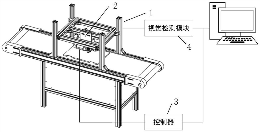
[0041] An embodiment of the present invention provides a rectangular multi-light source lighting device, including:
[0042] an adjustment bracket, the adjustment bracket includes a z-direction bracket and a movable frame which is arranged on the z-direction bracket and can move vertically along the z-direction bracket;
[0043] The lighting bracket includes a joint for connecting with the movable frame and a "well"-shaped frame located below the joint. The "well"-shaped frame extends in the circumferential direction to form four pairs of cantilevers, and the inner sides of the cantilevers are opposite to each other. It is used for erecting light sources, and the outside of the two opposite cantilevers is used for setting angle adjustment devices; the "well"-shaped frame is also provided with a shooting component at the bottom;
[0044] an object table, the object table is the area to be measured formed at the bottom of the lighting bracket;
[0045] a controller, at least us...
no. 2 example
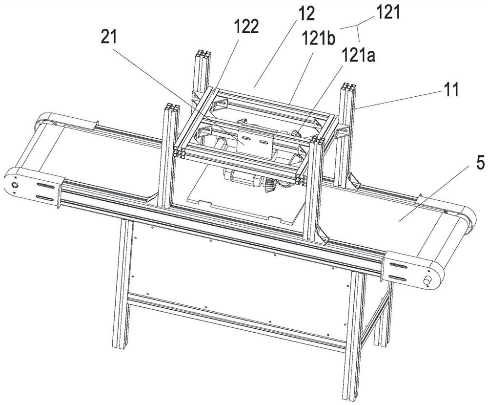
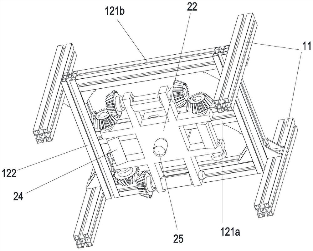
[0049] Please refer to Figure 1 to Figure 4 As shown, an embodiment of the present invention provides a rectangular multi-light source lighting device, including:
[0050] Adjusting bracket 1, the adjusting bracket includes a z-direction bracket 11 and a movable frame 12 which is arranged on the z-direction bracket 11 and can move vertically along the z-direction bracket 11;
[0051] The lighting bracket 2 includes a joint part 21 for connecting with the movable frame 12 and a "well"-shaped frame 22 located below the joint part 21, and the "well"-shaped frame 22 extends in the circumferential direction to form four pairs of cantilevers 23 , the inner side of the opposite cantilevers 23 is used to set up the light source 24, and the outer side of the opposite cantilever 23 is used to set the angle adjustment device; the "well"-shaped frame 22 is also provided with a shooting assembly 25 at the bottom;
[0052] an object table, the object table is the area to be measured forme...
no. 3 example
[0060] What is different from the second embodiment above is that the joint part is a first electric slider with a lighting bracket arranged on the first x-direction beam, and a second electric slider is also provided between the first x-direction beam and the y-direction beam. slider. The above-mentioned visual inspection module is also used to obtain the real-time image of the workpiece to be tested, and to determine the real-time geometric center point of the workpiece to be tested and the extra x offset of the camera assembly according to the real-time image, and the controller also uses According to the additional x offset, the position of the chute of the first electric slider on the first x-direction beam is controlled to determine the x-direction stroke of the lighting bracket, so that the camera assembly and the to-be-to-be- The real-time geometric center point of the measured workpiece maintains the preset x offset.
[0061] The visual inspection module is also used...
PUM
 Abstract
Description
Claims
Application Information
 - R&D
- Intellectual Property
- Life Sciences
- Materials
- Tech Scout
- Unparalleled Data Quality
- Higher Quality Content
- 60% Fewer Hallucinations
Browse by: Latest US Patents, China's latest patents, Technical Efficacy Thesaurus, Application Domain, Technology Topic, Popular Technical Reports.
© 2025 PatSnap. All rights reserved.Legal|Privacy policy|Modern Slavery Act Transparency Statement|Sitemap|About US| Contact US: help@patsnap.com


