
Microbubble generating device

A micro-bubble generation and water inflow technology, which is applied in transportation and packaging, mixers, mixing methods, etc., can solve the problems of reducing the use value of micro-bubbles, complex installation and fixing structures, and complex device structures, so as to reduce design difficulty and structure Simple, High-Precision Effects

Pending Publication Date: 2019-09-17
TONGJI UNIV
View PDF0 Cites 2 Cited by
  • Summary
  • Abstract
  • Description
  • Claims
  • Application Information

AI Technical Summary

Problems solved by technology

At present, the structure of the micro-bubble generating device is complicated, and some need pump assistance, and the increase of extra energy consumption reduces the use value of the micro-bubble
[0003] In the prior art, there is also a microbubble generating device that does not require an additional power device, but the structure is relatively complicated, it is inconvenient to disassemble and assemble, and the stability is also insufficient.
Especially for the design of the air intake channel, it is more difficult, and the installation and fixing structure is also more complicated

Method used


Image

  • Microbubble generating device
  • Microbubble generating device
  • Microbubble generating device

Examples


Embodiment 1

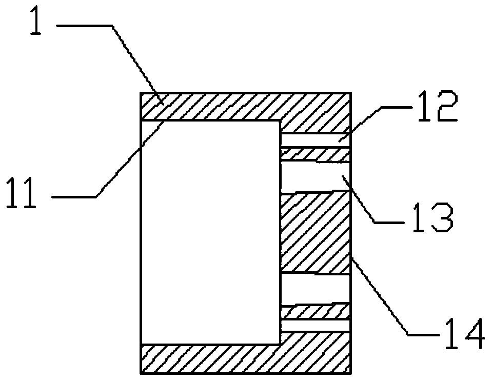
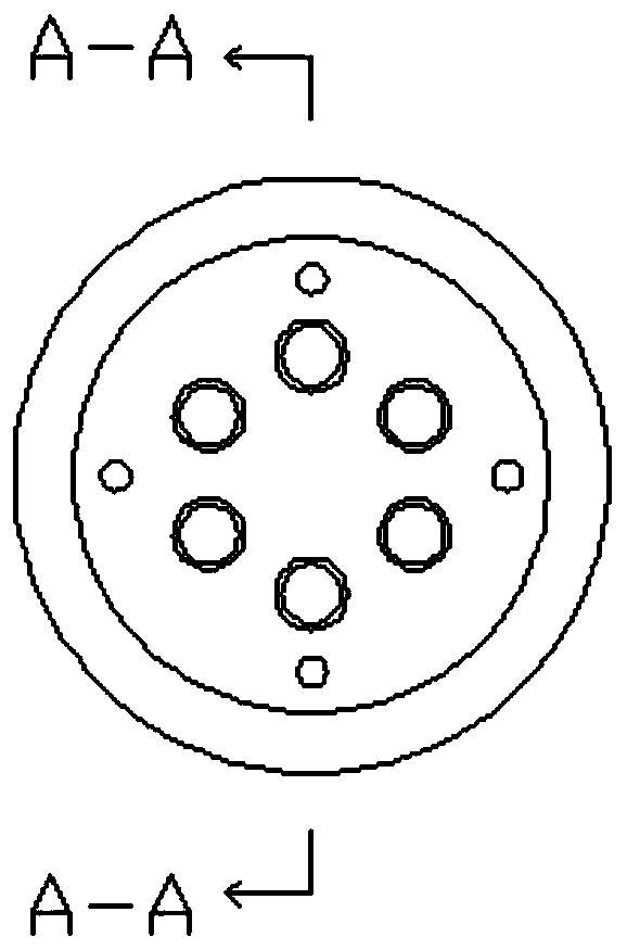
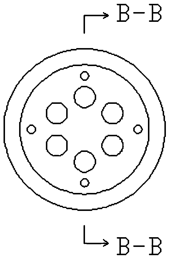
[0034] see Figure 1-9 , a micro-bubble generating device, comprising a water inlet part 1 and a water outlet part 2; the water inlet part 1 is in the shape of a cylinder, one end is an interface connected to a water supply pipeline, and the other end is along the circumference within the radial range of the interface. A group of first liquid passages 13 with decreasing axial inner diameters are provided in the direction, and a group of through holes 12 are arranged on the radially outer side of the first liquid passages 13; The end is a water outlet, and the front end is provided with a group of second liquid passages 22 corresponding to the first liquid passage 13 along the circumferential direction within the radial range of the water outlet. The inner diameter is larger than the inner diameter of the end of the first liquid channel 13; at least one layer of screen 3 is arranged in the water outlet; when the water inlet part 1 and the water outlet part 2 are docked, the gap...

Embodiment 2

[0046] The water outlet hole on the water outlet part 2 is not a threaded hole, but a through hole, and the blocking piece 4 is fixed with the through hole by means of interference fit.


PUM


Abstract

The invention relates to a microbubble generating device, comprising a water inlet part and a water outlet part; the water inlet part is cylindrical, one end is an interface connected to a water supply pipe, and the other end is provided with a set of first liquid passages of which the inner diameters in the axial direction decrease in a circumferential direction in a radial range of the interface; a set of through holes are formed in the radial direction outside the first liquid passages; the water outlet part is cylindrical, the front end is docked with the surface of the water inlet part, the rear end is a water outlet, and the front end is provided with second liquid passages in one-to-one correspondence with the first liquid passages in a circumferential direction in the radial range of the water outlet; the inner diameter of the second liquid passage is larger than the inner diameter of the tail end of the first liquid passage; at least one sieve is arranged in the water outlet; when the water inlet part and water outlet part are in surface-butted, a gap generated by the surface roughness is used to form an intake passage. The microbubble generating device disclosed by the invention has the advantages of simple structure, convenient disassembly and assembly, high stability and low price, and is very suitable for use in a municipal terminal, such as public places, households, and hotels.

Description

technical field [0001] The invention relates to a microbubble generating device, which belongs to the technical field of microbubble generation. Background technique [0002] Traditional air bubbles with a diameter of 1mm-5mm rise rapidly in water and disappear immediately after reaching the water surface, while micron-sized air bubbles with a diameter below 50μm rise slowly in water and have a large specific surface area, so the speed of gas-liquid mass transfer Much higher than traditional large-sized bubbles; at the same time, micron bubbles also have very good physiological effects. In recent years, micro-bubbles have not only been widely used in industrial fields such as air flotation, oxygen-enhancing aeration, and beverage deoxygenation, but are also increasingly used in civilian fields such as medical treatment, beauty care, and bathing. At present, the structure of the micro-bubble generating device is complicated, and some of them need water pump assistance, and t...

Claims


Application Information

Patent Timeline
IPC IPC(8): B01F5/04B01F5/06B01F3/04
CPCB01F23/235B01F23/2373B01F2025/9191B01F25/3121B01F25/31242B01F25/4523
Inventor 李攀廖正浩何怡霄
Owner TONGJI UNIV
Learn More